


Intel Desktop Board D915PGN/D915PSY/D915PCY/D915PCM Product Guide
60
You can obtain the BIOS update file through your computer supplier or by navigating to the
Desktop Board D915PGN/D915PSY/D915PCY/D915PCM page on the Intel World Wide Web site
at:
http://support.intel.com/support/motherboards/desktop
Navigate to the D915PGN/D915PSY/D915PCY/D915PCM page, click “[
view
]
Latest BIOS
updates
,”
and select the Iflash BIOS Update utility file.
NOTE
Review the instructions distributed with the update utility before attempting a BIOS update.
The Iflash Memory Update utility allows you to:
•
Update the BIOS in flash memory
•
Update the language section of the BIOS
Updating the BIOS
CAUTION
The AUTOEXEC.BAT file provided with the update files updates the BIOS. Do not interrupt the
process or the system may not function.
1. Boot the computer with the BIOS update diskette in drive A. During system boot, the
AUTOEXEC.BAT file provided with the update files will automatically run the BIOS update
process.
2. When the update process is complete, the monitor will display a message telling you to remove
the diskette and to reboot the system.
3. As the computer boots, check the BIOS identifier (version number) to make sure the update
was successful. If a logo appears, press
<Esc> to view the POST messages.
Recovering the BIOS
It is unlikely that anything will interrupt the BIOS update; however, if an interruption occurs, the
BIOS could be damaged. The following steps explain how to recover the BIOS if an update fails.
The following procedure uses recovery mode for the Setup program. See page 52 for more
information on Setup modes.
NOTE
Because of the small amount of code available in the boot block area, there is no video support.
You will not see anything on the screen during this procedure. Monitor the procedure by listening
to the speaker and looking at the diskette drive LED.
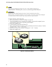
1. Turn off the computer, disconnect the computer’s power cord, and disconnect all external
peripherals.
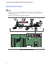
2. Remove the computer cover and locate the configuration jumper block (see Figure 27).