


Contents
vii
B Regulatory Compliance
Safety Regulations ..............................................................................................................69
European Union Declaration of Conformity Statement ........................................................69
Product Ecology Statements ...............................................................................................70
EMC Regulations ................................................................................................................71
Product Certification Markings (Board Level) ......................................................................72
Figures
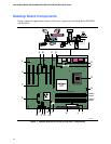
1. Desktop Boards D915PGN and D915PCY Components...............................................12
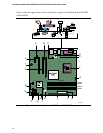
2. Intel Desktop Boards D915PSY and D915PCM Components.......................................14
3. Location of Standby Power Indicator.............................................................................24
4. Installing the I/O Shield.................................................................................................30
5. Desktop Board D915PGN and D915PCY Mounting Screw Hole Locations...................31
6. Lift Socket Lever...........................................................................................................32
7. Lift the Load Plate and Don’t Touch the Socket Contacts .............................................32
8. Remove the Protective Cover .......................................................................................33
9. Remove the Processor from the Protective Cover ........................................................33
10. Install Processor ...........................................................................................................34
11. Close the Load Plate ....................................................................................................34
12. Connecting the Processor Fan Heat Sink Cable to the Processor Fan Connector ........35
13. Dual Configuration Example 1 ......................................................................................36
14. Dual Configuration Example 2 ......................................................................................37
15. Dual Configuration Example 3 ......................................................................................37
16. Matching the Correct DIMM ..........................................................................................38
17. Installing a DIMM..........................................................................................................39
18. Removing the PCI Express x16 Card............................................................................41
19. Connecting the IDE Cable ............................................................................................42
20. Connecting the Serial ATA Cable .................................................................................43
21. Internal Headers ...........................................................................................................44
22. Back Panel Audio Connectors for Flexible 6-Channel Audio System ............................47
23. Location of Fan Headers...............................................................................................48
24. Connecting 2x10 Power Supply Cables ........................................................................49
25. Connecting 2x12 Power Supply Cables ........................................................................50
26. Location of the PCI Bus Add-in Card and Peripheral Interface Connectors for
Desktop Boards D915PGN and D915PCY....................................................................51
27. Location of the BIOS Configuration Jumper Block ........................................................52
28. Back Panel Connectors ................................................................................................54
29. Removing the Battery ...................................................................................................58
Tables
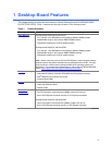
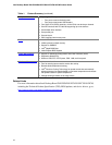
1. Feature Summary...........................................................................................................9
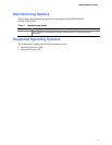
2.
Manufacturing Option....................................................................................................11
3. Desktop Boards D915PGN and D915PCY Components...............................................13
4. Desktop Boards D915PSY and D915PCM Components...............................................15
5. Desktop Board D915PGN/D915PSY Memory Configurations.......................................17
6. Desktop Board D915PCY/D915PCM Memory Configurations.......................................17
7. RJ-45 10/100 Ethernet LAN Connector LEDs...............................................................20
8. Front Panel Audio Header Signal Names......................................................................45