Desktop Board Features
23
Fan Connectors
The desktop boards have one 4-pin processor fan header.
Desktop boards D915PGN and D915PCY have three chassis fan headers. Desktop boards
D915PSY and D915PCM have two chassis fan headers. See Figure 23 on page 48 for the location
of the fan headers.
Fan Speed Control (Intel
®
Precision Cooling Technology)
Intel Precision Cooling Technology automatically adjusts the processor fan speed based on the
processor temperature and adjusts the chassis fan speeds depending on the system temperature.
System fan noise may be reduced by operating controlled chassis and processor fans at the
minimum necessary speeds.
NOTE
Not all chassis fan headers on desktop boards D915PGN and D915PCY are controlled. Refer to
Table 3 on page 13 to identify controlled chassis fan headers.
The processor and chassis fan speed control features can be disabled independently through the
desktop board BIOS. Disabling the processor fan speed control will result in the fan operating at
full speed if it is not a self controlled fan. It is recommended that processor fan speed control
remain enabled (default BIOS setting) when using the processor fan heat-sink included with Intel
boxed processors. Disabling the chassis fan speed control results in chassis fans always operating
at full speed. The chassis fan speed control feature should be disabled if a self-controlled chassis
fan is attached to any controlled chassis fan header.
The overall system noise reduction will vary based on system configuration and environment.
Suspend to RAM (Instantly Available PC Technology)
CAUTION
For Instantly Available PC technology, the 5 V standby line for the power supply must be capable
of delivering adequate +5 V standby current. Failure to provide adequate standby current when
using this feature can damage the power supply and/or effect ACPI S3 sleep state functionality.
Instantly Available PC technology enables the board to enter the ACPI S3 (Suspend-to-RAM) sleep
state. While in the S3 sleep state, the computer will appear to be off. When signaled by a wake-up
device or event, the system quickly returns to its last known awake state.
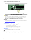
The desktop board’s standby power indicator, shown in Figure 3, is lit when there is standby power
to the system. This includes the memory modules and PCI bus connectors, even when the
computer appears to be off.
If the system has a dual-colored power LED on the front panel, the sleep state is indicated by the
LED turning amber.


