


Intel Desktop Board D915PGN/D915PSY/D915PCY/D915PCM Product Guide
36
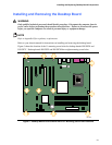
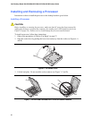
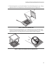
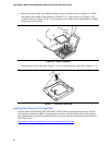
Installing and Removing Memory
NOTE
To be fully compliant with all applicable Intel
®
SDRAM memory specifications, the boards require
DIMMs that support the Serial Presence Detect (SPD) data structure. You can access the PC
Serial Presence Detect Specification at:
http://www.intel.com/technology/memory/pcsdram/spec/
Desktop boards D915PGN and D915PCY have four 184-pin DDR DIMM sockets arranged as
DIMM 0 (blue) and DIMM 1 (black) in both Channel A and Channel B.
Desktop boards D915PSY and D915PCM have four 240-pin DDR2 DIMM sockets arranged as
DIMM 0 (blue) and DIMM (black) 1 in both Channel A and Channel B.
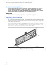
Figure 17 shows the DIMM socket locations.
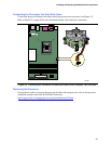
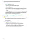
Guidelines for Dual Channel Memory Configuration
Before installing DIMMs, read and follow these guidelines for dual channel configuration.
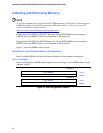
Two or Four DIMMs
Install a matched pair of DIMMs equal in speed and size (see Figure 13) in DIMM 0 (blue) of both
channels A and B.
Channel A
1 GB, 400 MHz
DIMM 0
DIMM 1
Channel B
1 GB, 400 MHz
DIMM 0
DIMM 1
Figure 13. Dual Configuration Example 1