


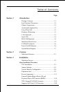
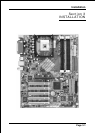
Introduction
Page 1-6
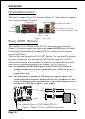
Power-On/Off (Remote)
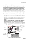
The board has 20-pin ATX and 4-pin ATX12V connectors for power supplies
(Figure 4). For power supplies that support the Remote On/Off feature, this should
be connected to the mainboard front panel PW_ON connector for the computer
power On/Off button.
The board has been designed with Soft Off" function. You can turn off the system
two ways: pressing the front panel power On/Off button, using the "Soft Off"
function (incorporated in the mainboards onboard circuit controller) that can be
controlled by an operating system such as Windows
®
XP/ME/2000/98/95.
Note: For maintaining the DDR SDRAM power during STR (ACPI S3) function, it is
strongly recommend to use power supplies that have a +5VSB current of (>=)
2A. Please check the 5VSBs specification that has been printed on the power
supplys outer case.
Note: The board requires a minimum of 250 Watt power supply to operate. Your
system configuration (amount of memory, add-in cards, peripherals, etc.) may
exceed the minimum power requirement but to ensure that adequate power is
provided, use a 300 Watt (or greater) power supply.
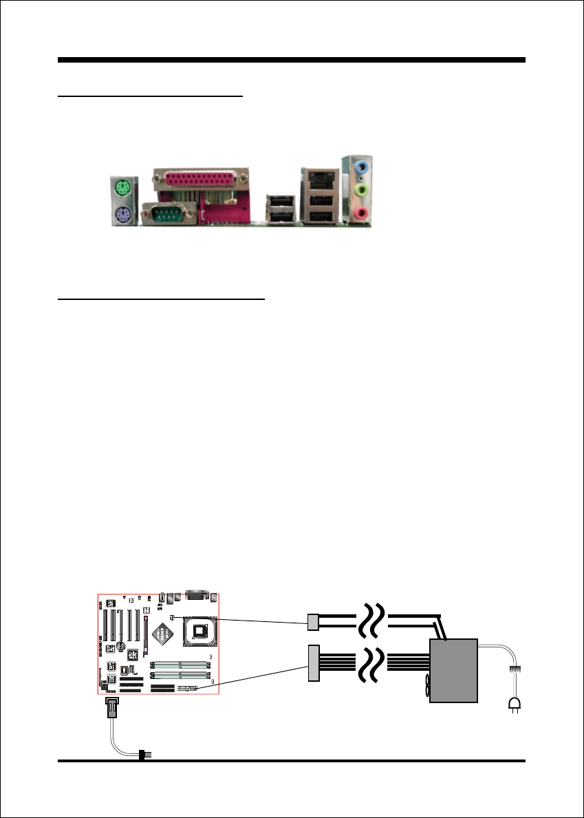
I/O Shield Connector
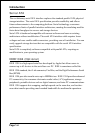
The board is equipped with an I/O back panel (Figure 3). Ensure that your computer
case has the appropriate I/O cutout.
Figure 3: I/O ports
PW-ON
Case (chassis) Power ON/OFF button (PW-ON)
POWER SUPPLY
12V 4-pin
20-pin
Figure 4: Simple ATX power ON/OFF controller
COM1
Parallel Port
RJ-45 LAN
(Optional)
USB2.0
ports
USB2.0
ports
PS/2
Mouse
PS/2
Keyboard
Mic-in/Center&Subwoofer (Pink)
Line-out/Front out (Green)
Line-in/Rear out (Blue)