


Installation
Page 3-12
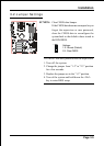
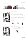
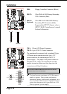
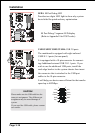
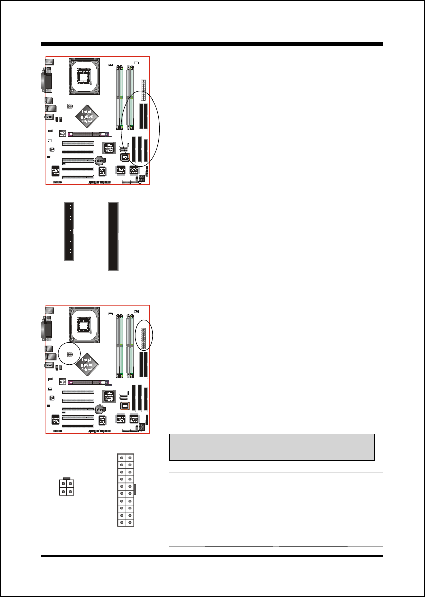
FDD: Floppy Controller Connector (Black)
IDE1/2: Ultra DMA-66/100 Primary/Secondary
IDE Connector (Blue)
IDE3/4: Ultra DMA-66/100 & RAID Primary/
Secondary IDE Connector (Red)
Supported by HPT372 chipset, refer to
HPT372 RAID Controller users manual
for detail information.
PW1
PW12
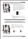
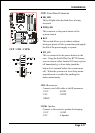
PW1: 20-pin ATX Power Connector
PW12: 4-pin ATX12V Power Connector
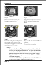
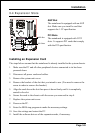
The mainboard is equipped with a standard 20-pin
ATX main power connector and a 4-pin +12V
power connector for connecting an ATX12V
power supply. The plugs of the power cables are
designed to fit in only one orientation. Find the
proper orientation then insert the plugs into the
connectors until they fit in place.
Caution:
Be sure that the PW1 and PW12 Power Connector must be used
simultaneously or else can not boot-up.
40 39
2
1
IDE1/IDE2
34 33
2
1
FDD
!!
!!
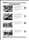
! The board requires a minimum of 250 Watt power
supply to operate. Your system configuration
(amount of memory, add-in cards, peripherals, etc.)
may exceed the minimum power requirement but to
ensure that adequate power is provided, use a 300
Watt (or greater) power supply.
!
-12V3.3V
Gronud+5V
PS-ON+5V
-5VPW-OK
+5V5VSB
+5V+12V
+12V+12V
"
3.3V3.3V
GronudGronud
GronudGronud
GronudGronud
GronudGronud
PW1
PW12
IDE1IDE2
IDE3
IDE4
FDD
(Optional)