


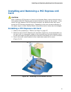
Installing and Replacing Desktop Board Components
45
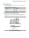
HD Audio Link Header
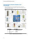
See Figure 21, A for the location of the HD Audio Link header. Table 5 shows the pin
assignments for the header.
Table 5. HD Audio Link Header Signal Names
Pin Signal Name Pin Signal Name
1 BCLK 2 Ground
3 RST# 4 DVDD_IO
5 SYNC 6 Ground
7 SDO 8 3.3V_DVDD_CORE
9 SDI0 10 +12 V
11 SDI1 12 Key
13 No Connection 14 3.3V_DUAL
15 No Connection 16 Ground
S/PDIF Connector
Figure 21, B shows the location of the S/PDIF connector. Table 6 shows the pin
assignments and signal names for the S/PDIF connector.
Table 6. S/PDIF Connector Signal Names
Pin Description
1 Vcc
2 S/PDIF Out
3 Ground
Front Panel HD Audio Header
Figure 21, C shows the location of the front panel audio header. Table 7 shows the pin
assignments for the front panel audio header.
Table 7. Front Panel Audio Header Signal Names
Pin Signal Name Pin Signal Name
1 PORT 1L 2 GND
3 PORT 1R 4 PRESENCE#
5 PORT 2R 6 SENSE1_RETURN
7 SENSE_SEND 8 KEY (no pin)
9 PORT 2L 10 SENSE2_RETURN