


Intel Desktop Board DP45SG Product Guide
48
Alternate Front Panel Power LED Header
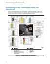
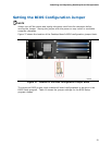
Figure 23, G shows the location of the alternate front panel power LED header. Pins 1
and 3 of this header duplicate the signals on pins 2 and 4 of the front panel header. If
your chassis has a three-pin power LED cable, connect it to this header.
Table 12 shows the pin assignments and
signal names for
the alternate front panel
power LED header.
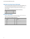
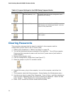
Table 12. Alternate Front Panel Power LED Header Signal Names
Pin Description In/Out
1 Front panel green LED Out
2 No pin
3 Front panel yellow LED Out
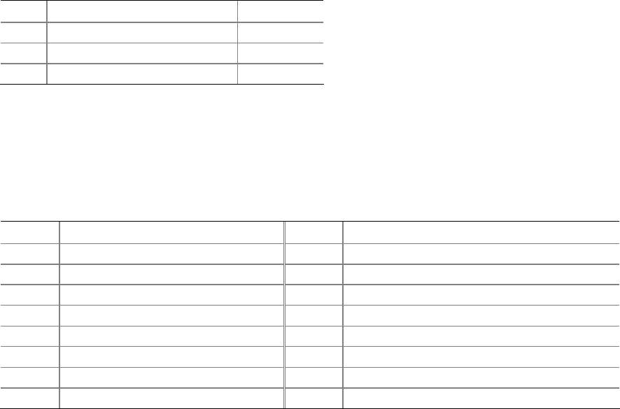
HD Audio Link Header
Figure 23, I shows the location of the HD Audio Link header. Table 13 shows the pin
assignments and signal names for the HD Audio Link header.
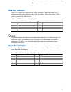
Table 13. HD Audio Link Header Signal Names
Pin Signal Name Pin Signal Name
1 BCLK 2 Ground
3 RST# 4 DVDD_IO
5 SYNC 6 Ground
7 SDO 8 3.3V_DVDD_CORE
9 SDI0 10 +12 V
11 SDI1 12 Key
13 No Connection 14 3.3V_DUAL
15 No Connection 16 Ground