34 Intel
®
Xeon™ Processor, Intel
®
E7520 Chipset, Intel
®
6300ESB ICH Development Kit User’s Manual
Debug Procedure
6.2 Level 2 Debug (Power Sequence)
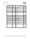
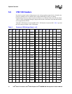
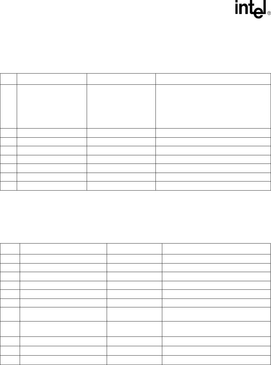
Check the items in Table 7 below if “SYSTEM PWRGD” is not illuminated.
6.3 Level 3 Debug (Voltage References)
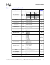
Table 8 includes the first items to look at when debugging a board that does not boot.
Table 7. Level 2 Debug (Power Sequence)
Item Test Pass/Fail Criteria Cause of Failure
1 Primary power supply voltages
Measure voltage across:
• C3K2: 3.3 V
• C3K1: -12 V
• C4K3: 5 V
• C4K2: 5 V
• C4K5: 12 V
External power supply failure
2 1.8 V C9E14: 1.8 V DDR2 power supply failure
3 1.5 V C5C5: 1.5 V MCH/PXH/ICH core power supply failure
4 1.8 VSBY C9G5: 1.8 V DDR2 standby power supply failure
5 CPU VTT power supply C9H10: 1.2 V CPU_VTT power supply failure
6 CPU0 VRD L9J2: 1.2 V - 1.4 V CPU0 VRD Failure
7 CPU1 VRD L5J1: 1.2 V – 1.4 V CPU1 VRD Failure
8 Verify “SYSTEM PWRGD” LED CR2H1: Green Power Sequence Failure
Table 8. Level 3 Debug (Voltage References)
Item Test Pass/Fail Criteria Cause of Failure
1 MCH DDR2 Channel A Vref R6D4: 0.9 V Vref incorrect: check resistor values
2 MCHDDR2 Channel B Vref R6B3: 0.9 V Vref incorrect: check resistor values
3 MCH Hublink Vref R5F11: 0.354 V Vref incorrect: check resistor values
4 MCH Hublink Vswing R5F8: 0.804 V Vswing incorrect: check resistor values
5 ICH Hublink Vref R4G7: 0.347 V Vref incorrect: check resistor values
6 ICH Hublink Vswing R4G4: 0.696 V Vswing incorrect: check resistor values
7
CPU0 VTT Vref
(Back side of board)
R2U5: 0.775 V
R2V2: 0.775 V
Vref incorrect: check resistor values
8
CPU1 VTT Vref
(Back side of board)
R4U5: 0.754
R5V1: 0.754
Vref incorrect: check resistor values
9
MCH VTT Vref R6F2: 0.775 V Vref incorrect: check resistor values
10
DIMM A DDR2 Vref R3M1: 0.9 V Vref incorrect: check resistor values
11
DIMM B DDR2 Vref R2M1: 0.9 V Vref incorrect: check resistor values


