FS-979 User’s Manual I/O Port Pin Assignment
Parallel Port 47
A.5 < Parallel Port>
2
26
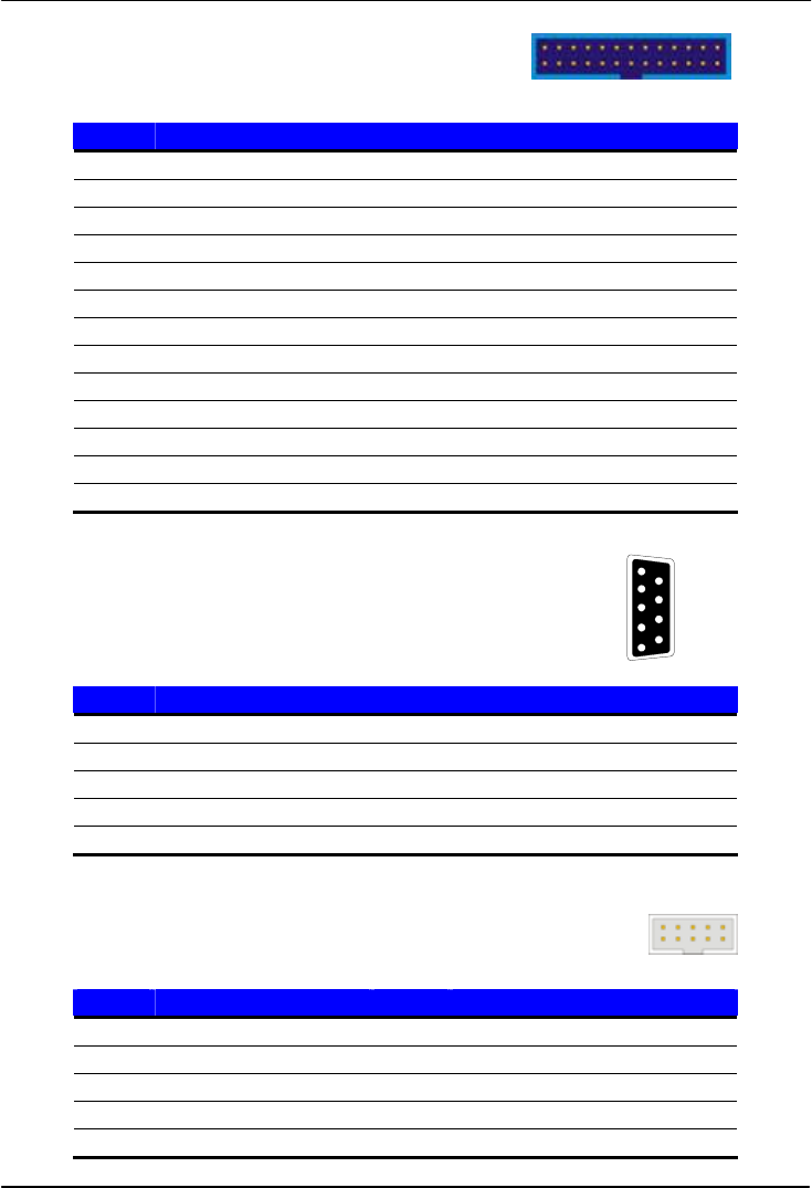
Connector: CN_LPT
Type: 26-pin (2 x 13) 2.54-pitch box header
1 25
Pin Description Pin Description
1 STROBE- 14 AUTO FEED-
2 D0 15 ERROR-
3 D1 16 INITIALIZE-
4 D2 17 SELECT INPUT-
5 D3 18 Ground
6 D4 19 Ground
7 D5 20 Ground
8 D6 21 Ground
9 D7 22 Ground
10 ACKNOWLEDGE- 23 Ground
11 BUSY 24 Ground
12 PAPER EMPTY 25 Ground
13 SELECT+ 26 N/C
A.6 <Serial Port>
1
2
3
4
5
6
7
8
9
A.6.1 <External DB9 serial port>
Connector: COM1
Type: 9-pin D-sub male connector on bracket
Pin Description Pin Description
1 DCD 6 DSR
2 SIN 7 RTS
3 SO 8 CTS
4 DTR 9 RI
5 Ground
2 10
A.6.2 <Internal serial port>
Connector: CN_COM1 (VDG2/VDG3 only); CN_COM2
1
9
Type: 10-pin (2 x 5) 2.54-pitch header
Pin Description Pin Description
1 DCD 2 SIN
3 SO 4 DTR
5 Ground 6 DSR
7 RTS 8 CTS
9 RI 10 N/C


