


INSTALLATIONS
IB850 User’s Manual 25
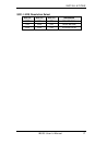
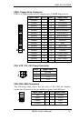
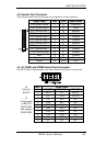
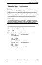
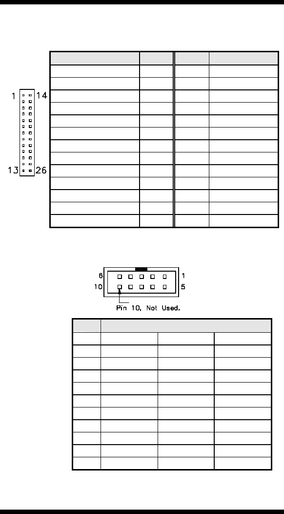
J2: Parallel Port Connector
The following table describes the pin out assignments of this connector.
Signal Name Pin # Pin # Signal Name
Line printer strobe 1 14 AutoFeed
PD0, parallel data 0 2 15 Error
PD1, parallel data 1 3 16 Initialize
PD2, parallel data 2 4 17 Select
PD3, parallel data 3 5 18 Ground
PD4, parallel data 4 6 19 Ground
PD5, parallel data 5 7 20 Ground
PD6, parallel data 6 8 21 Ground
PD7, parallel data 7 9 22 Ground
ACK, acknowledge 10 23 Ground
Busy 11 24 Ground
Paper empty 12 25 Ground
J2
Select 13 N/A N/A
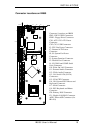
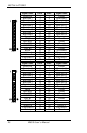
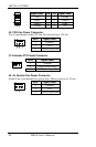
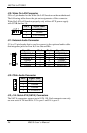
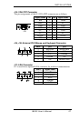
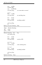
J4, J5: COM1 and COM2 Serial Ports Connector
J4 and J5 both 10-pin headers, are the onboard serial port connectors.
Pin #
Signal Name
RS -232 RS-422 RS-485
1 DCD TX- DATA-
2 RX TX+ DATA+
3 TX RX+ NC
4 DTR RX- NC
5 GND GND GND
6 DSR RTS- NC
7 RTS RTS+ NC
8 CTS CTS+ NC
9 RI CTS- NC
J4
Fixed as
RS-232
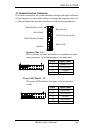
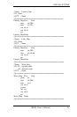
J5
Configurable
as RS-232/
RS-422/485
with jumpers
JP2/JP3/JP4
10 NC NC NC