


IMB200 LGA775 ATX MB User Manual
20 Hardware Description
Chapter 4 Hardware Description
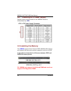
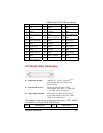
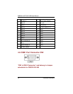
4.1 General Output Connector: CN37
Power LED
Pins 1, 3, 5, 7 connect the system power LED indicator to its
respective switch on the case. Pin 1 is +, and pin 5 is assigned
as -.Pin 7 is defined as NC
External Speaker and Internal Buzzer
Connector
Pins 2, 4, 6, 8 connect to the case-mounted speaker unit or
internal buzzer.
Hardware Reset
Pins 11 & 12 were designed for Hardware Reset.
HDD Activity LED
This connector extends to the hard drive activity LED on the
control panel. This LED will flash when the HDD is being
accessed. Pins 13 & 14 connect the hard disk drive and the
front panel HDD LED.
Power Button
This 2-pin connector was designed at Pin9/10