


38 Evaluation Platform Board Manual
Intel
®
IQ80332 I/O Processor
Hardware Reference Section
3.9 Switches and Jumpers
3.9.1 Switch Summary
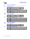
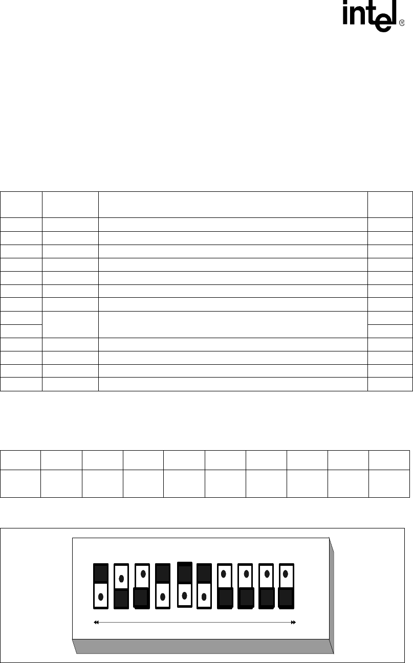
Please note that the term ‘open’ refers to the individual pin of switch S7A1 being pushed in at bottom
(small dot on pin away from the ‘open’ label on the switch). The term ‘closed’ refers to the pin being
pushed in at the top. Please see Figure 11, “Default Switch Setting Switch S7A1” on page 38, for
more details.
3.9.2 Default Switch Settings of S7A1- Visual
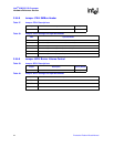
Table 15. Switch Summary
Switch Association Description
Factory
Default
S1C1 80332 Reset
S6A1 BPCI-X Reset
S7A1-1 APCI-X Bus PCI-XBus A Speed Set Closed
S7A1-2 IOP RESET: Sets IOP Reset-Mode operation Open
S7A1-3 IOP RETRY: Sets IOP RETRY-Mode operation Open
S7A1-4 BPCI-X Bus PCI-X Bus B speed set Closed
S7A1-5 BPCI-X Bus PCI-X Bus B Hot Plug Reset Closed
S7A1-6
BPCI-X Bus
SMBUS Bus
Hot Plug Capable Disable
SMBUS Manageability address bit 5
Closed
S7A1-7 Open
S7A1-8 SMBUS Bus SMBUS Manageability address bit 3 Open
S7A1-9 SMBUS Bus SMBUS Manageability address bit 2 Open
S7A1-10 SMBUS Bus SMBUS Manageability address bit 1 Open
S8A1 CPLD Rotary Switch Position 1
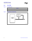
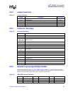
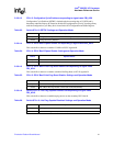
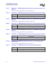
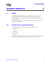
Table 16. Switch S7A1
Closed Open Open Closed Closed Closed Open Open Open Open
S7A1
1
S7A1
2
S7A1
3
S7A1
4
S7A1
5
S7A1
6
S7A1
7
S7A1
8
S7A1
9
S7A1
10
Figure 11. Default Switch Setting Switch S7A1
165432
78
9
10
Open