


User’s Manual
48
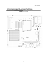
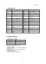
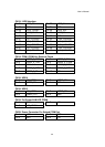
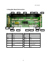
1. Connectors
Connector
Function
Connector
Function
CN1 Inverter CONN
CN20 Power Connector For
Extend COM Port
CN2 LED
CN21 Programmable Keyboard
CN3 USB5/6
F3 CPU FAN CONTROL
CN4 LINE-IN CONN
F4 SYSTEM FAN
CONTROL
CN7 Speaker & MIC CONN
DIMM1 DDR Memory
CN8 I-Bottom CONN
IDE1 2.5” IDE Device
CN9 Support VFD
PWR1 PWR CONN
CN10 Card Reader Connector
PWR2 DC JACK
CN12 LCD Interface
RJ45_1 LAN Connector
CN13 100 pin Connecter to IO
Board
CF1 CF CARD CONN
CN14 COM5 CONN for Touch
AUX1 LINE OUT
CN17 Power Switch
AUX2 MIC IN
CN19 For Power/LAN LED
CONN
USB1 USB 3 / USB4 port
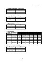
2. Jumper Settings
1. CMOS Operation Mode
Function JP1
CMOS Normal
◎N/C
CMOS Reset 1-2
To clear the CMOS:
1) Remove AC power from the unit.
2) Open the cabinet.
3) Change the JP1 jumper setting from N/C to 1-2.
4) Wait 1 minute.
5) Change the JP1 jumper setting back to N/C.
6) Close the cabinet.
7) Apply AC power and continue.