


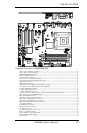
INSTALLATIONS
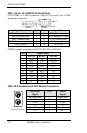
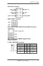
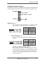
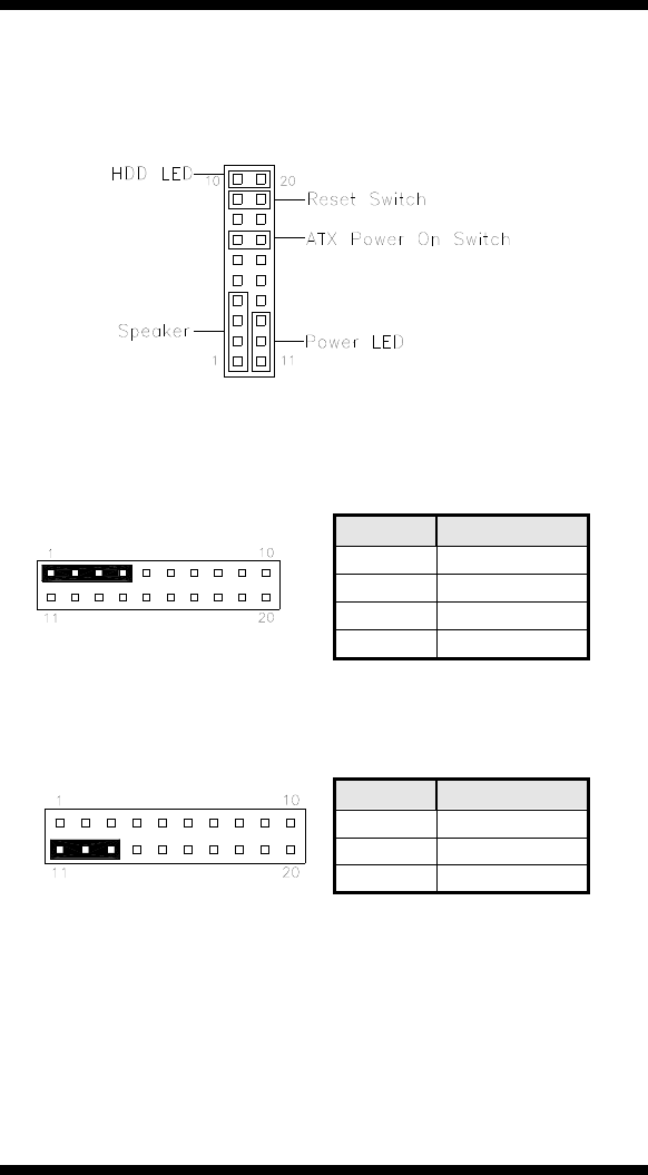
J8: System Function Connector
J8 provides connectors for system indicators that provide light indication
of the computer activities and switches to change the computer status.
Speaker: Pins 1 - 4
This connector provides an interface to a speaker for audio
tone generation. An 8-ohm speaker is recommended.
Pin # Signal Name
1 Speaker out
2 No connect
3 Ground
4 +5V
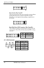
Power LED: Pins 11 - 13
The power LED indicates the status of the main power
switch.
Pin # Signal Name
11 Power LED
12 No connect
13 Ground
ATX Power ON Switch: Pins 7 and 17
This 2-pin connector is an “ATX Power Supply On/Off
Switch” on the system that connects to the power switch on
the case. When pressed, the power switch will force the
system to power on. When pressed again, it will force the
system to power off.
MB898 User’s Manual 21