INSTALLATIONS
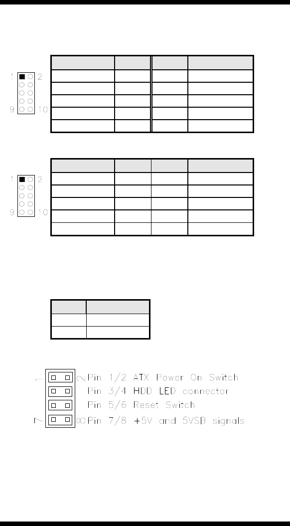
J3: Digital I/O Connector (4 in, 4 out)
This 10-pin digital I/O connector supports TTL levels and is used to
control external devices requiring ON/OFF circuitry.
Signal Name Pin # Pin # Signal Name
Ground 1 2 +5V
Out3 3 4 Out1
Out2 5 6 Out0
IN3 7 8 IN1
IN2 9 10 IN0
J4: Audio Front Header
Signal Name Pin # Pin # Signal Name
MIC2_L 1 2 Ground
MIC2_R 3 4 Presence#
Line2_R 5 6 MIC2_ID
Sense 7 8 NC
Line2_L 9 10 Line2_ID
J5: For LPC I/F Adaptor Card
Supports ID394 with Fintek F81216, 2 or 4 serial ports
J6: SPDIF Out Connector
Pin # Signal Name
1 SPDIF out
2 Ground
MI940 User’s Manual 17
J7: System Function Connector
ATX Power ON Switch: Pins 1 and 2
This 2-pin connector is an “ATX Power Supply On/Off Switch” on the
system that connects to the power switch on the case. When pressed, the
power switch will force the system to power on. When pressed again, it
will force the system to power off.


