


Mechanical Requirements
R
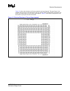
12 mPGA604 Socket
Mechanical Design Guide
3.5 Markings
All markings required in this section must be able to withstand a temperature of 240 ºC for 40
seconds (minimum) typical of a reflow profile for solder material used on the socket, as well as any
environmental test procedure outlined in
Section 5.
3.5.1 Name
mPGA604 (Font type is Helvetica Bold – minimum 6 point).
This mark shall be molded or Laser Marked into the processor side of the socket housing.
Manufacturer’s insignia (font size at supplier’s discretion).
This mark will be molded or laser marked into the socket housing. Both marks must be visible when
first seated in the motherboard. Any request for variation from this marking requires a written
description (detailing size and location) to be provided to Intel for approval.
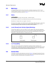
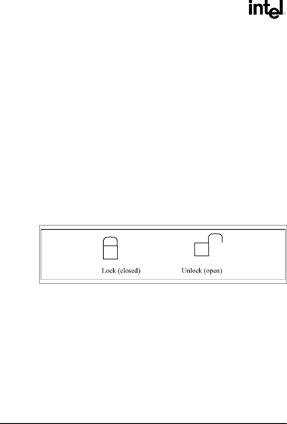
3.5.2 Lock (Closed) and Unlock (Open) Markings
The universal symbols for ‘Lock’ and ‘Unlock’ are to be marked on the socket in the appropriate
positions. Clear indicator marks must be located on the actuation mechanism that identifies the lock
(closed) and unlock (open) positions of the cover as well as the actuation direction. These marks
should still be visible after a package is inserted into the socket.
3.5.3 Lot Traceability
Each socket will be marked with a lot identification code that will allow traceability of all
components, date of manufacture (year and week), and assembly location. The mark must be placed
on a surface that is visible when mounted on a printed circuit board. In addition, this identification
code must be marked on the exterior of the box in which the units ship.
3.6 Socket Size
The socket size must meet the dimensions as shown in Section 9, allowing full insertion of the pins
in the socket, without interference between the socket and the pin field. The mPGA604 Socket and
actuation area must fit within the keep-in zone defined in
Section 9.