


10 Intel® Blade Server Fibre Channel Expansion Card SBEFCM4, 4 Gbps: Installation and User’s Guide
Note: The loop reset delay, adapter hard loop ID, and hard loop ID settings are not applicable.
Host adapter BIOS: When this option is disabled, the read-only memory (ROM) BIOS code on the
Fibre Channel Expansion Card is disabled, freeing space in upper memory.
Frame size: This setting specifies the maximum frame length supported by the Fibre Channel
Expansion Card.
Spin up delay: When this option is enabled, the BIOS code waits up to 5 minutes to find the first
drive.
Connection options: This setting defines the type of connection (loop or point-to-point) or
connection preference (see Table 3).
Fibre Channel tape support: This setting is reserved for Fibre Channel tape support. The default is
Enabled.
Data rate: This setting determines the data rate.
Note: The Fibre Channel Expansion Card settings and default values will vary, based on the
version of BIOS code installed for the expansion card.
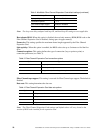
Hard loop ID 0-125
Spin up delay Enabled or Disabled
Connection Options 0, 1, 2
Fibre Channel tape support Enabled or Disabled
Data rate 0, 1, 2, 3
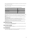
Table 3. Fibre Channel Expansion Card connection options
Option Type of connection
0 Loop only
1 Point-to-point only
2 Loop preferred; otherwise, point-to-point
Table 4. Fibre Channel Expansion Card data rate options
Option Data rate
0 1 Gb per second
1 2 Gb per second
2 Auto select
3 4 Gbper second
Table 2. Modifiable Fibre Channel Expansion Card default settings (continued)