


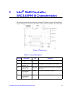

13 Intel® RAID Controller SRCSASPH16I Hardware Guide
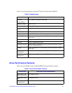
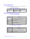
Technical Specifications
The design and implementation of the Intel
®
RAID Controller SRCSASPH16I minimizes
electromagnetic emissions, susceptibility to radio frequency energy, and the effects of
electrostatic discharge. See the appendices for regulatory marks and certifications.
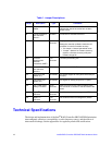
J6 Dirty Cache LED
Header
SFF8087 For connection to enclusure LED. When lit,
indicates the data in the cache has not been
written to disk.
J9 Internal SAS/SATA
port connector,
ports 4-7
SFF8087 Connection to SAS/SATA devices.
J11 Mode 0 select 2-pin
connector
No jumper is required for normal operation.
Setting the controller to Mode 0 holds the I/O
processor in reset for firmware recovery.
• "No Jumper = Normal operational mode.
• "Jumper = Mode 0 for firmware recovery,
requires a firmware recovery utility and
firmware image file.
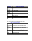
J12 Universal
Asynchronous
Receiver/
Transmitter (UART)
4-pin
connector
For factory and debug use.
J13 Internal SAS/SATA
port connector,
ports 0-3
SFF8087 Connection to SAS/SATA devices.
J14 Drive Fault LED
Header (0-7)
8x2 header LED signal support for front panel drive fault per
port (0-7).
J15 Port activity LED
header (0-7)
8x2 header LED signal for activity per port for 0-7 ports.
J16 Intel
®
RAID Smart
Battery Connector
20-pin
connector
Cable connector for the extrernal battery pack.
This connector is located on the back side of the
board.
J17 Keyed I
2
C
connector
3-pin
connector
Out-of-band enclosure management (SES2).
J18 Keyed I
2
C
connector
3-pin
connector
Out-of-band enclosure management (SES2).
Table 1. Jumper Descriptions
Jumper Description Type Comments