


11
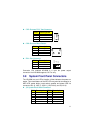
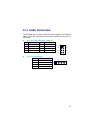
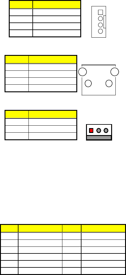
CN2: External VCC Out Connector
PIN Description
1 VCC
2 GND
3 GND
4 VCC
1
4
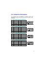
CN4: External Reset Button
PIN Description
1 RST_SW
2 GND
3 GND
4 GND
1
2
3
4
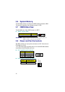
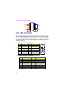
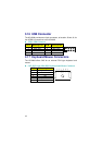
FN1: Fan Connector
PIN Description
1 GND
2 +5V
3 N/C
13
GND
+5V
N/C
Connector FN1 onboard HS-2606 is a 3-pin fan power output
connector. And HS-2606 supports +5V Fan only.
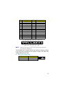
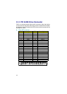
3.9 System Front Panel Connectors
The HS-2606 has one LED at location J2 that indicates the power-on
status. This visual feature of the IDE LED may also be connected to a
HDD LED, power button, reset switch, speaker and power LED via
connector J2(1-3), J2(5-7), J2(9-11), J2(2-4-6-8), and J2(10-12).
J2: System Front Panel Connector
PIN Description
PIN
Description
1 330
Ω
Pull +5V 2 Speaker
3 HDD LED 4 N/C
5 PW Button 6 GND
7 GND 8 330Ω Pull +5V
9 Reset Switch 10 330
Ω
Pull +5V
11 GND 12 PW_LED