Intel
®
Xeon™ Processor, Intel
®
E7520 Chipset, Intel
®
6300ESB ICH Development Kit User’s Manual 5
Contents
Figures
1Intel
®
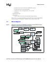
Xeon™ Processor with 800 MHz System Bus and Intel
®
E7520 and Intel
®
6300ESB Customer Reference Board Block Diagram .................................................................9
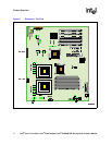
2 Placement - Top View.................................................................................................................10
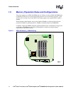
3 DDR2 400 Memory - DIMM Ordering .........................................................................................12
4Intel
®
Xeon™ Processor with 800 MHz System Bus and Intel
®
E7520 and Intel
®
6300ESB Customer Reference Board Jumper...........................................................................21
5 Power Distribution Block Diagram ..............................................................................................25
6 Clock Block Diagram ..................................................................................................................26
7 Platform Reset Diagram .............................................................................................................27
8 SMBus Block Diagram................................................................................................................28
9 IRQ Routing Diagram .................................................................................................................29
10 Power Buttons ............................................................................................................................32
11 Components Requiring Heat Sink Assembly..............................................................................35
12 Inserting Processor in Socket.....................................................................................................36
13 Cleaning the Processor Surface.................................................................................................36
14 Installing the Processor Backplate..............................................................................................37
15 Removing the Protective Covers ................................................................................................37
16 Installing the Heatsink.................................................................................................................38
Tables
1 Related Documents ......................................................................................................................7
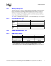
2 Supported DIMM Module Types.................................................................................................11
3 DIMM Placement DDR2 400 ......................................................................................................11
4 Jumper Settings..........................................................................................................................22
5 Processor VRD Settings.............................................................................................................30
6 Level 1 Debug (Port 80/BIOS) ....................................................................................................33
7 Level 2 Debug (Power Sequence)..............................................................................................34
8 Level 3 Debug (Voltage References)..........................................................................................34
9 Components Requiring Heat Sink Assembly..............................................................................35


