


8
English
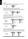
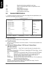
F_AUDIO (Front Audio Connector)
Connects to the audio connector located on the front panel of the system casing
(dependent on case design). When use of the front panel audio connector is required,
please remove the 5-6 pin, 9-10pin jumper.
Please note that use of only the front panel audio connector or the rear panel audio connector
is permitted.
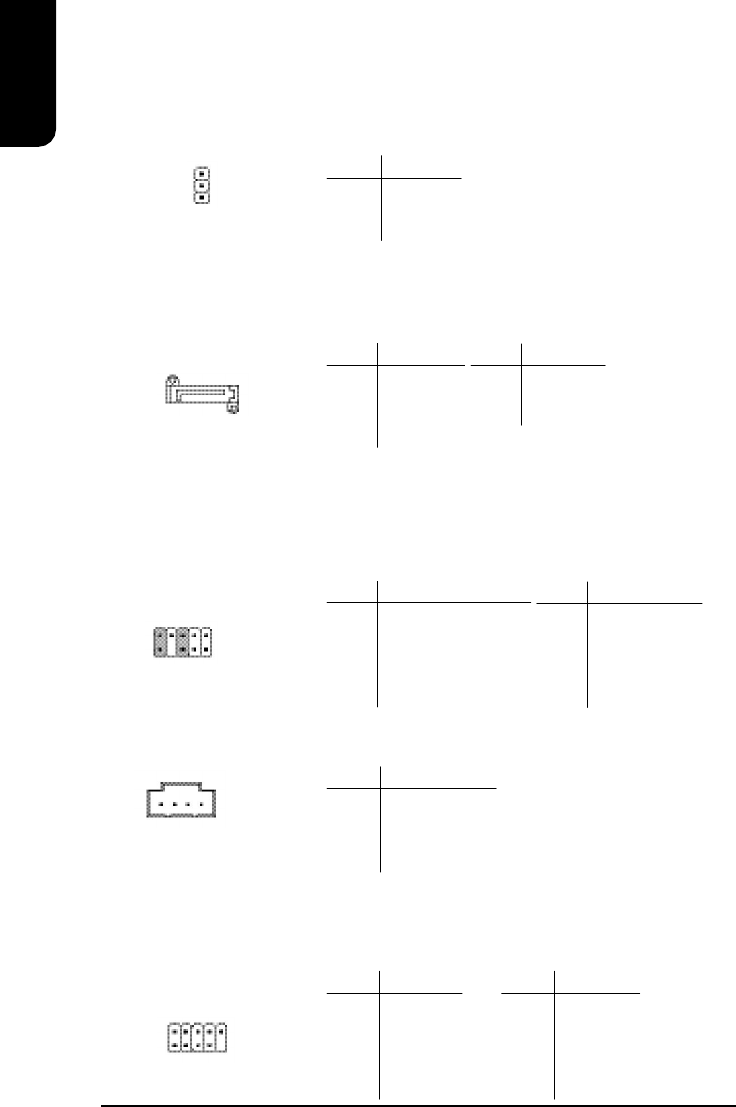
CD_IN (Optical Drive Audio Connector)
Connects CD-ROM or DVD-ROM audio connector.
PIN SIGNAL
1 CD_L
2 GND
3 GND
4 CD_R
PIN SIGNAL
1 MIC
2 GND
3 MIC_BIAS
4 POWER
5 Front Audio (R)
PIN SIGNAL
6 Rear Audio (R)
7 Reserved
8 NO PIN
9 Front Audio (L)
10 Rear Audio (L)
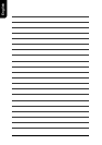
PWR_LED
Connects to the system power LED indicator whereby the power is indicated as ON or OFF.
However, the indicator will flash when the system is suspended.
PIN SIGNAL
1 MPD+
2 MPD-
3 MPD-
1
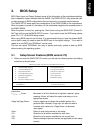
SATA0/SATA1 (Serial ATA Connector, controlled by ICH5)
The SATA0/1 connector is able to connect a single Serial ATA device via a SATA cable.
For the connected SATA hard disk to work correctly, please check the related BIOS setting
and install proper driver for the SATA controller.
PIN SIGNAL
5 RXN
6 RXP
7 GND
PIN SIGNAL
1 GND
2 TXP
3 TXN
4 GND
7
1
1
10
9
2
F_USB1 (Front USB Connector)
Connects to the USB connector located on the front panel of the system casing (dependent on
case design). Note: Please make sure that each USB connection matches its designated
position. If connections are made incorrectly, the result can lead to inability to use the function
or even damage.
PIN SIGNAL
6 USB Dy+
7 GND
8 GND
9 NO PIN
10 NC
PIN SIGNAL
1 POWER
2 POWER
3 USB Dx-
4 USB Dy-
5 USB Dx+
1
2
10
1
9