


6 EasyLAN Wireless Interface Kit Installation Instructions
Chapter 2 — Physical Installation
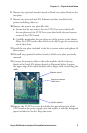
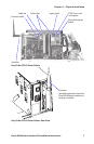
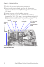
Connect the EasyLAN adapter board to the PCI connector (J84) on
the CPU board so the hole in the board becomes aligned with the
spacer and secure the board with the #T20 Torx screw.
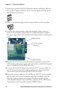
Route the antenna cable over the SIMMs on the CPU board towards
the rear plate and secure it using the cable clips included in the kit.
One clip is factory-fitted on the EasyLAN adapter board and the
other should be fitted in the small hole at the top of the CPU board
immediately to the rear of the memory SIMM sockets.
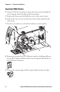
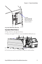
From the inside of the electronics compartment, insert the antenna
connector through the round hole in the rear plate and lock it with
the washer and nut on the outside.
Fit the antenna to the connector of the antenna cable and bend the
hinge so the antenna points straight up.
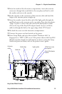
From the outside, insert the thin end of the light guide through the
small hole next to the antenna on the rear plate. Press the clear plastic
“lamp” in place. Connect the other end to the black plastic socket
(D1) at the top of the EasyLAN adapter board. Secure it with the
cable tie through the hole at the upper edge of the CPU board.
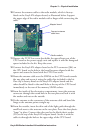
Put back the cover over the electronics compartment.
Route the cable from the display unit above the ribbon motor.
Connect the cable to connector J50 at the upper front corner of the
CPU board.
Connect the power cord and switch on the power.
Enter the Setup Mode and print the test label “Hardware Info” in
Fingerprint or “HW” in IPL to see if the printer detects the EasyLAN
Wireless interface board. For information on how to enter the Setup
Mode and print test labels, refer to the printer’s user’s guide.
15
16
17
18
19
20
21
22
23