


Hermes Operator Note Page 5 of 32
2 CONNECTIONS & INDICATIONS
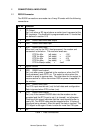
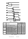
2.1 RS232 Connector
The RS232 connections are made via a 9 way D female with the following
connections:
Pin No. Function
1 CD Output
Set (+ve) when a RF signal above a certain level is present at the
RF connector. The threshold is programmable over 10 levels that
are defined in section 5.13
2 RXD RS232 data level data output
3 TXD RS232 level data input
4 DTR RS232 level input
When set (+ve) by the DTE (host processor) the modem and
transceiver is turned on. The max/min levels are:
DTR Vin Min. (off state) = -15V
DTR Vin Max. (off state) = +2.5V
DTR Vin Min (on state) = +5V
DTR Vin Max (on state) = +15V
DTR Iin Max(on state) = 4mA
5 Signal Ground
6 DSR RS232 level output
Set (+ve) after power is applied to the modem or when the DTE
(host processor) sets DTR +ve. The output is active when the
modem is ready to receive data. The time taken for the output to
become active is <50ms from when DSR or power is applied to
the modem.
7 RTS RS232 level input
The RTS input must be set (+ve) for both data and configuration.
Data is ignored when RTS is clear (-ve).
8 CTS RS232 level output
Set (+ve) if the transmit RS232 data into the modem can be
accepted and the RTS input is set, it is cleared (-ve) otherwise.
Clearing of this signal indicates that the input transmit buffer is
nearly full .The RS232 data must be stopped within 10 bytes of
this signal being cleared. After this point the data is ignored. The
CTS signal is set again if there is room for more than 10 bytes.
9 n/c
Table 1 Data Connections