


Hermes Operator Note Page 6 of 32
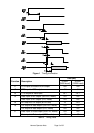
2.2 Power Connector
The power and ancillary connections are made via a 9 way D male
connector. The power supply input is fully isolated from the chassis of the
module.
Note: The power supply cannot be used as an RS232 input line.
Pin No. Function
1 RSSI Received Signal Strength Output
Analogue output proportional to the level of the RF input
Level at -110dBm input = ~0.6V and at -60dBm = ~2.1V
2 n/c
3, 4 +ve Supply Input (9 - 36VDC)
Receive current <100mA at 24VDC input
Transmit current <400mA at 1000mW RF output, 24VDC input
(reverse voltage protection with re-settable "polyfuse")
5 Power Supply Ground (isolated from enclosure)
6 I
2
C Bus Clock (engineering use only)
7 0V (chassis of enclosure)
8 I
2
C Bus Data (engineering use only)
9 Power Supply Ground (isolated from enclosure)
Table 2 Power Connections
2.3 RF Connector
The RF connection to the modem is a female TNC bulkhead connector.
2.4 Front Panel Indications
There are 3 LED indicators which show the operation of the unit as follows:
P Green Power On when DC supply input present and DTR input
is high (> 3V)
S Orange Status Flashes orange when the transceiver is switched
to transmit or receive. Continuous orange if the
transceiver goes “Out Of Lock” (OOL) which
happens on failure, or when an invalid frequency
is programmed into it.
T Red TX On when the transmitter is turned on.
These LEDs are next to the connectors on both types of enclosure.