Model 335 Supplement 8
WARNING!!!
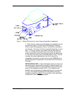
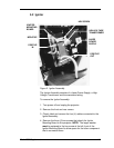
The Squirrel Cage blower (see Figure 1), next to the Arc Lamp
Assembly, is not covered by a grill. Use extreme caution near this
blower when performing any adjustments or maintenance that
require the projector cover to be removed with power on.
WARNING!!!High voltage exists on the Ignitor Board
Assembly at the front, left of the projector. Be careful when
reaching over this area when the Arc Lamp is operating. Wear
proper safety clothing to avoid shock hazard. Also wear safety
goggles to protect your eyes from Ultraviolet and Infrared
exposure.
1. The Xenon Arc Lamp may have moved within the reflector. To
check this, look at the anode shadow on the blue dichroic mirror
(the blue dichroic mirror is the first mirror after the condensing
lens). Verify that the anode shadow (small, dark oval inside the
light circle) is a uniform oval that is no more than 1/2 inch or no
less than 1/4 inch in diameter. If the oval looks non-uniform or has
a flare coming from one side, adjust the X-Y plates on the back of
the lamphouse (see Figure 1). Use a standard Phillips screwdriver
and loosen the two top screws on the pivot holes and slide the
plates on their pivots until the shadow looks uniform. While
viewing Test Pattern 6 (Static Flat Field) the uniformity on the
screen should become more centered also.
2. Adjust the Z-axis of the Xenon Arc Lamp. (This procedure will
probably be required if the lamp has been in use for a long time.)
Use a 9/64 inch hexhead balldriver and rotate the screwhead
located on the black ball on the rear of the lamphouse (see Figure
1). Only a turn or two should be required. Observe the screen or
use a light meter to verify proper brightness (refer to step 8 below
for details on how to measure the screen brightness). Be sure to
maintain proper Roll-Off (refer to NOTE ON ROLL-OFF below
Step 3).


