


4343
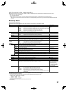
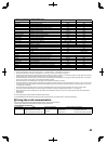
<Functions controlled by the MAKE/TRIGGER system>
Display Functions to be controlled Opening Short-circuiting
– – – No function — —
Tally Color
Tally lamp color selection*
1
Green Red
Tally Type
Tally lamp lighting method selection Whole One half at a time
Tally-L(R)
Light the left half of the tally lamp in red*
2
Off On
Tally-R(G)
Light the right half of the tally lamp in green*
2
Off On
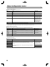
SDI-1
Changes the input to “SDI 1” Invalid Valid
SDI-2
Changes the input to “SDI 2” Invalid Valid
HDMI
Changes the input to “HDMI” Invalid Valid
Video/Component
Changes the input to “VIDEO/COMPO.” Invalid Valid
Marker
The marker indication Off On
Center Marker
The center marker indication Off On
Frame
Indication of the area of the specified aspect ratio Off On
Marker Select
Selects the items of “Marker”*
3
Non-“R-” items “R-” items
Manual Aspect
Changes the aspect ratio 4:3 16:9
1:1
Displays in 1:1 mode Off On
Status
Status display*
4
☞ “On the Status Display” on page 30
Level Meter
Audio level meter display *
5
Time Code
Time code display Off On
Source ID
☞ “Source ID” in “Information” on page 39
*
6
Color Off
Color off Color Monochrome
Screens Check
Screens check *
7
I/P Mode
Change a mode according to a input picture *
8
Muting
Muting on/off Off On
Dimmer
Change the intensity of the button lamps Normal Dark
Wave Form
Wave form display Off On
Vector Scope
Vector scope display Off On
Histogram
Histogram display Off On
Dynamic
Adjusts the picture to be suitable for a bright place Invalid Valid
Zebra Mode *
9
Zebra mode Invalid Valid
Focus Assist Mode *
9
Focus assist mode Invalid Valid
*
1
Can be controlled when “Tally Type” (“Set-Up Menu” → “Function Setting” → “Tally Setting”) is set to “Normal”.
*
2
Can be controlled when “Tally Type” (“Set-Up Menu” → “Function Setting” → “Tally Setting”) is set to “Half”.
*
3
Selects which functions in “Marker” are activated, non-“R-” items or “R-” items. (☞ “Marker” on page 34)
*
4
Displays the information shown when INPUT SELECT button of the current input is pressed. (☞ “On the Status Display” on page 30) While controlling
with the MAKE system, the information is displayed only at the moment of short-circuiting.
*
5
While controlling with the MAKE system, the level meter is switched between displayed (short-circuiting) and hidden (opening). When “Level Meter
Display” is set to “Off,” the level meter is not displayed (“No Effect” appears).
While controlling with the TRIGGER system, the pattern of the audio channel display is switched.
*
6
While controlling with the MAKE system, the available set-up options will be the setting value currently selected in “Source ID” (“On” or “Auto” [short-
circuiting]) and “Off” (opening). While controlling with the TRIGGER system, uses the same set-up option as those in the Set-Up Menu. (☞ “Source ID”
in “Information” on page 39)
*
7
While controlling with the MAKE system, the screen is switched between normal screen (opening) and blue screen (short-circuiting). While
controlling with the TRIGGER system, the screen changes in the same way as when pressing SCR. CHK. button (☞ 7 on page 27).
*
8
Must be controlled with the TRIGGER system. The mode is switched between “Normal” and “Cinema” (This function cannot be controlled with the
MAKE system).
*
9
DT-F9L5 Only.
● You cannot assign the same function to different pin terminals.
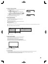
● The TRIGGER system switches each function by short-circuiting the pin terminal for about 1 second and opening it.
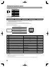
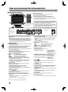
Using the serial communication
You can control the monitor from a personal computer etc. via the RS-232C terminal.
* Consult your dealer for the details of the external control specification.
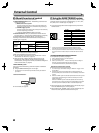
<Communication specifications>
Input terminal Cable Terminal specification Communication specifications
RS-232C A straight cable with a D-sub 9-pin
connector (male for the monitor,
female for the personal computer etc.)
☞ page 44
Baud Rate: 4800 bps Stop Bits: 1 bit
Data Bits: 8 bits Flow Control: No control
Parity: No parity Communication Code: ASCII Code