


6
Parts Identification (Continued)
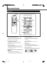
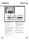
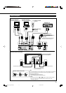
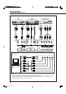
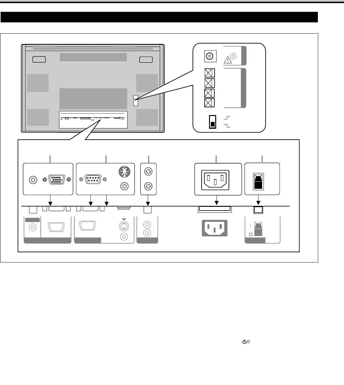
Monitor: Rear Views
AC INAUDIO
L
OUT
R
RGB A
AUDIO
IN
REMOTE
RS-232C
WIRED
MAKE
EXTERNAL
(
9
9
(
R
SPEAKER OUT
L
INTERNAL
POWER
OPTION
1 2 3 4 5
7
8
6
1 RGB A input terminals (page 11)
Input terminal (D-sub, 15 pin)
Connect to the video output terminal of a personal
computer.
Note:
• Use a cord as short as possible when connecting a
personal computer to this terminal. (Recommended
length is within 3 m.)
AUDIO IN terminal (stereo mini jack)
Connect to the audio output terminal of a personal
computer.
2 REMOTE terminals (pages 11 and 13)
RS-232C terminal (D-sub, 9 pin)
Connect to the RS-232C terminal of a personal computer.
For the control method using this terminal, consult an
authorized JVC dealer.
MAKE terminal (mini DIN, 4pin)
Connect an external control unit. (See page 13.)
WIRED terminal (stereo mini jack)
Connect a wired remote control unit to this terminal.
Note:
• When the above three terminals are used at the same
time, transmitted commands through the MAKE
terminal have priority over those through the other
terminals.
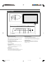
3 AUDIO OUT terminals (pin jack) (page 11)
Connect to the audio input terminals of external
equipment such as an amplifier.
4 AC IN terminal (page 11)
Connect the supplied power cord to this terminal.
5 POWER switch (page 14)
When this switch is set to “| (on),” you can turn on and
off (on standby) the Monitor by using the POWER button
on the remote control or the
button on the Monitor.
6 OPTION terminal (page 13)
Connect the power cord of the Cooling Fan Unit (not
supplied) when installing the Monitor vertically.
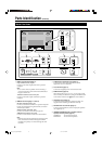
7 SPEAKER OUT L/R terminals (page 11)
Connect external speakers, such as unique JVC speakers
(not supplied), etc.
8 INTERNAL/EXTERNAL (built-in speaker/external
speaker) selecting switch (page 11)
INTERNAL: To use built-in speakers.
EXTERNAL: To use external speakers.
EN_04_13_GM_V42C.p65 04.1.14, 1:22 PM6