1-6 (No.XE003)
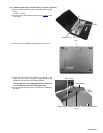
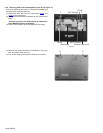
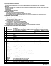
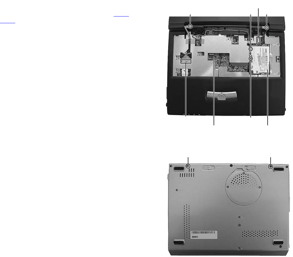
3.1.6 Removing LCD panel assembly(See Figure 10 and Figure 11)
• Prior to the following procedure, the keyboard assembly and
the hinge cover should be removed.
(1) Disconnect each wire from the connectors CON2 and
CON9 on the main board.
(2) Remove two wires from the connector on the wireless LAN
board.
*Connect grey wire to the AUX terminal, and black wire
to the MAIN terminal for reassembly.
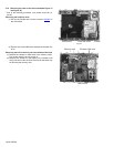
(3) Remove two screws F which are attached to the hinge.
Fig.10
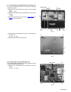
(4) Remove two screws G which are attached to the hinge
from the bottom of the main unit.
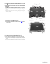
(5) Pull out the hinge by moving the LCD panel unit upward.
Fig.11
Main board
MAIN Terminal
AUX Terminal
Wireless LAN board
FF
CON2
CON9
G G


