


8 Hardware Installation
Kingston Technology Company EtheRx User’s Guide - Rev. B00
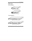
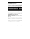
8 or 16 UTP Port LEDs
The LINK/ACTIVITY/PARTITION LEDs use two colors to display three
states of operation for the 8 or 16 UTP ports. If a good link is established on
any given port, the green LED will be continuously lit, indicating a valid
network connection between the network node and the hub. When data is
received, the LED will flash green. A flash may be longer or shorter
depending on the length of the data packet being received. If the port is
partitioned, it will display solid red.
If the LED does not display solid green indicating a good link, check the
following:
1. Make sure the power is turned on for both the PC
and EtheRx hub. The power LED should be lit.
2. Verify the network adapter has loaded its drivers from the
PC. Some network adapters require the drivers to be loaded
to establish a proper link.
3. Make sure the correct cable type is selected.
4. Make sure the cable is wired properly and connected
on both ends.
5. If steps 1, 2, 3, and 4 are correct, the cable may be
defective or not wired correctly. Replace the cable and try
again. Please refer to Appendix A for pin assignments and
Appendix B for cabling guidelines.
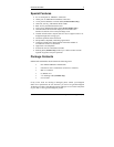
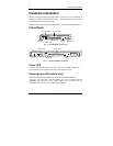
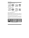
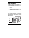
Cascade Switch
The Cascade Switch provides cable wiring flexibility on the last UTP Port (i.e.,
Port 8 or Port 16) for connecting to a workstation or cascading to another hub.
By default, the last UTP port is set to “Crossover” (left side) as a standard,
internally-crossed port, or MDI-X port. Depending on the wiring of your UTP
cable (normally “Straight-Through”), the port is used to connect a workstation.
For cascading to
another hub using a straight-through cable, move the Cable
Switch to “Straight-Through” (right side). If a crossover UTP cable is used to
cascade to another hub, leave the Cable Switch in the “Crossover” position.
See Figure 1-3 for a diagram showing the 16-Port KNE16TP/WG model. To
verify the pin wiring of your UTP cable, refer to “Appendix B Cabling
Guidelines” on page 17.