


RCA 2600 Series Installation/Operation Guide
Page 3 of 10
Rev C
KELLY MANUFACTURING COMPANY
KMC
KMC Publication No.1401-1
SECTION 1: INSTRUMENT DESCRIPTION
1.1 GENERAL DESCRIPTION
An attitude indicator, also known as a gyro horizon or articial horizon, is an instrument used in an aircraft to inform the pilot of the
orientation of the airplane relative to the earth. It indicates pitch (fore and aft tilt) and bank (side to side tilt), and is a primary instru-
ment for ight in instrument meteorological conditions. Attitude indicators also have signicant applications under visual ight rules.
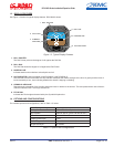
The RCA 2600 Digital Electronic Attitude Indicator receives digital information from a series of accelerometers which is processed
to actuate a display that has two dimensions of freedom, simultaneously displaying pitch and bank. The display is colored to
indicate the horizon as the division between the two colored segments (blue for sky and brown for ground), and is intended to be
intuitive to use. The actual bank angle is calibrated around the circumference of the instrument dial. The pitch angle is indicated by
a series of calibration lines, each representing 5° or 10° of pitch. Unlike digital multifunction type displays, the RCA 2600 display is
not cluttered with additional information so that the pilot has instant attitude recognition.
Because the RCA 2600 has no mechanical gyroscope, it is much more stable than traditional horizons. The unit is designed to
work in 360 degrees of pitch and roll and, unlike a mechanical unit, the RCA 2600 can tolerate angles in pitch and roll that would
cause a gyroscopic unit to tumble.
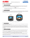
On the attitude indicator you will see two yellow horizontal lines with a dot between them. The horizontal lines represent the wings
and the dot represents the nose of the aircraft. If the symbolic airplane dot is above the horizon line (more blue background) - the
aircraft is nose up. If the symbolic airplane dot is below the horizon line (more brown background) - the aircraft is nose down.
When the dot and wings are on the horizon line, you are in level ight. If the lines representing the wings roll to the left or the right,
the aircraft is probably starting a turn.
1.2 PHYSICAL DESCRIPTION
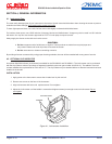
The RCA 2600 indicator is a direct reading instrument which provides a visual display of aircraft pitch and roll in reference to the
horizon. The instrument utilizes a series of accelerometers and complex mathematical formulas to determine pitch and roll. There
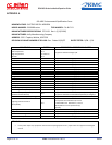
is no external inputs to the instrument. Refer to table 1.1 below for leading particulars. There are two basic models of the RCA
2600 Series; the RCA 2600-2 which is the 2” version and the RCA 2600-3 which is the 3” version.
OPERATING VOLTAGE .......................................................................................................................................... 9 to 32VDC
STARTING CURRENT ............................................................................................................9VDC: 0.18 to 0.22 AMPs MAX
RUNNING CURRENT ......................................................................................(14VDC SYSTEM) ..................0.20 AMP MAX
(28VDC SYSTEM) ..................0.15 AMP MAX
CIRCUIT BREAKER SIZE............................................................................................................................................... 2 AMP
SETTLING ERROR ...........................................................................................................1º MAXIMUM IN ROLL AND PITCH
OPERATING TEMPERATURE RANGE .............................................................................................................-30º TO +50º C
MATING CONNECTOR ........................................................................................................MS3116E8-4S OR EQUIVALENT
WEIGHT ...........................................................................................................RCA2600-3 ...........................................6.5 oz
RCA2600-2 ...........................................4.5 oz
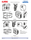
DIMENSIONS/PANEL CUTOUT .......................................................................................................................SEE FIGURE 1
EYE VIEWING ANGLE ENVELOPE ....................................................................Horizontal Left and Right: 35° Left, 35° Right
Vertical Up and Down: 35° Up, 35° Down
Minimum distance from display surface: 6 inches
Maximum distance from display surface: 48 inches
FAA SPECIFICATION CONFORMANCE ..........................................................TS0-C4c, TSO-C113, DO-160F and DO-178B
EASA SPECIFICATION CONFORMANCE ...................................................................................ETSO-C4c and ETSOC-113
MEETS OR EXCEEDS ..........................................................................................................................AS8034A and AS396B
TABLE 1.1, LEADING PARTICULARS