


Page 6 of 10
RCA 2600 Series Installation/Operation Guide
Rev C
KELLY MANUFACTURING COMPANY
KMC
KMC Publication No.1401-1
SECTION 2, INSTALLATION
2.1 GENERAL INFORMATION
The conditions and test required for the TSO approval of this article are minimum performance standards. It is the responsibility of
those installing this article either on or within a specic type or class of aircraft to determine that the aircraft installation conditions
are within the TSO standards. TSO articles must have a separate approval for installation in an aircraft. The article may be installed
only if performed under 14CFR Part 43 or the applicable airworthiness requirements.
For certain classes of Part 23 aircraft level C of DO-178B certication may not be sufcient - check with your local regulatory
authority prior to installation.
2.2 HANDLING
Although the RCA 2600 Series instruments are totally electronic, improper handling can cause damage. Please observe the
following precautions while handling.
1. Do not drop, jar or shake instrument. Store instrument in shipping container until installation.
2. Instruments should be transported in the original shipping container when moved to and from aircraft. If container is not
available, carefully carry by hand in upright position.
3. Avoid touching the screen. This is the most vulnerable part of the instrument. Improper handling and cleaning can cause
permanent scratching of the screen surface (See Instrument Care on Page 8).
4. To prevent further damage, a malfunctioning instrument should be handled as carefully as a new instrument. Most mal-
functioning instruments can be repaired and returned to service. Contact Kelly Manufacturing Company for repair and
warranty information.
2.3 PRE-INSTALLATION INSPECTION
1. When the instrument is rst received, inspect container for any shipping damage.
2. Carefully remove the instrument from shipping container and retain container for later storage or shipping.
3. Inspect the instrument for any signs of damage. Contact your Shipper to le any claim due to shipping damage.
4. Check labeling on the instrument to assure that the instrument panel tilt angle is correct for your aircraft.
2.4 INSTALLATION
Install the instrument on the aircraft by using the aircraft manufacturer’s recommendations and by the following steps:
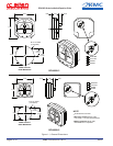
1. The RCA 2600 Series Horizon uses standard panel cutouts. Refer to gure 1.1 “General Dimensions” for instrument
and cutout dimensions.
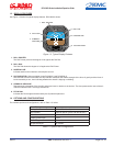
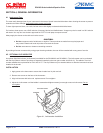
2. Instrument Pinout is: A = GND, B = PWR, C = SPARE, D = SPARE. Pinout information may also be found on the
back of the instrument. See table 1.1 “Leading Particulars” for additional electrical information.
3. Attach aircraft electrical connector to the instrument and insert into the instrument panel cutout.
4. Secure instrument with user supplied screws. Use 6-32 UNC-2b screws or equivalent. Screw length should not
exceed .5 inches plus bezel and panel thickness. Do not tighten.
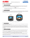
5. With the aircraft on level surface, apply power to the instrument and allow it to warm up for 3 minutes.
6. Adjust roll position of the instrument by visually aligning the symbolic airplane with the horizon line as indicated
on the instrument and tighten screws.
-WARNING-
Do Not modify the instrument in any way. Any modications will void the warranty and revoke the FAA
certications. This includes, but is not limited to, actions such as enlarging the mounting holes.