


Replacements and Installations
SM5440-1 – 18NOV97 13
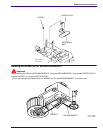
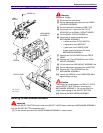
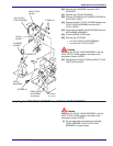
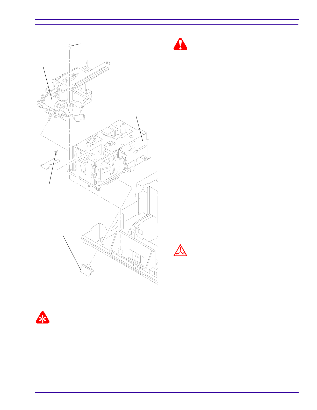
Replacing the MECHANISM ASSEMBLY
Warning
Dangerous Voltage
[1] Disconnect the main power.
[2] Do the replacement procedure for the LOWER
HOUSING ASSEMBLY.
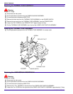
[3] Cut and remove the necessary WIRE TIES.
[4] Disconnect the 2 wires from the CYCLE
SOLENOID on the SMALL CIRCUIT BOARD.
[5] Pull the SMALL CIRCUIT BOARD up.
[6] Disconnect all wires connected to the
MECHANISM ASSEMBLY:
• 1 yellow wire from CYCLE SWITCH
• 1 orange wire from WIRE NUT
• 1 green wire from POWER CORD
• 2 green ground wires from the lower
MECHANISM ASSEMBLY
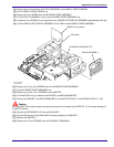
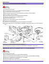
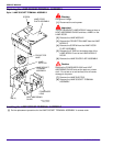
[7] Remove the FOCUS KNOB from the FRONT
PANEL.
[8] Remove the 3
Torx
SCREWS from the LENS
MOUNT ASSEMBLY.
[9] Lift and move the LENS MOUNT ASSEMBLY up.
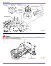
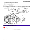
[10] Do the replacement procedure for the MOTOR.
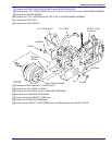
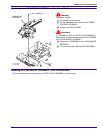
[11] Remove the 3
Torx
SCREWS from the
MECHANISM ASSEMBLY.
[12] Loosen the SCREW on the STABILIZER WALL
approximately half way.
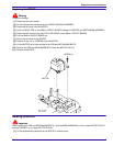
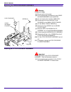
Caution
There might be a bind between the SELECT LEVER
and the SELECT BUTTON when removing the
MECHANISM ASSEMBLY. Do not use force; this
might cause damage to the SELECT BUTTON.
[13] Remove the MECHANISM ASSEMBLY.
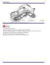
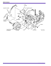
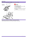
Installing the MECHANISM ASSEMBLY
Important
To insert the SELECT BUTTON into the hole in the SELECT LEVER when installing the MECHANISM ASSEMBLY,
hold the SELECT BUTTON completely down.
[1] Do the removal procedure for the MECHANISM ASSEMBLY in reverse order.
A091_4047CA
ASSEMBLY
MECHANISM
FOCUS KNOB
SCREW
MOUNT
LENS
SCREW (3)
A091_4047CCA