


Adjustments
SM5440-1 – 18NOV97 29
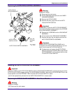
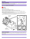
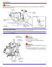
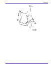
[10] Bend the AUTO-FOCUS BRACKET ASSEMBLY MIRROR until the image is within the target on the TARGET
SLIDE. Use ADJUSTMENT TOOL TL-3005 or the SPRING HOOK TL-1165.
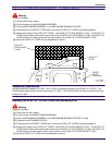
Adjustment Specification
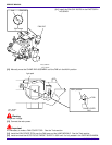
Use TL-3002 to observe the focus light path and check the light image. Use T-BAR TL-3003 to bend the
PHOTOCELL BRACKET to move the NULL in the center if necessary.
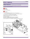
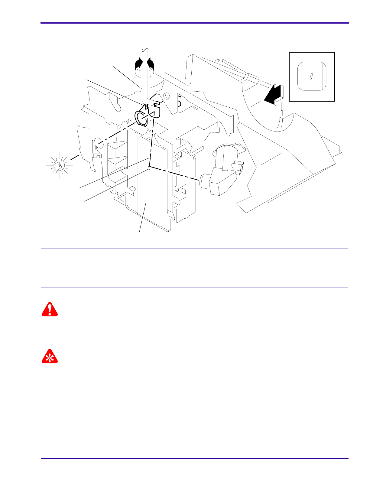
Adjusting the NULL
Warning
Dangerous Voltage
[1] Disconnect the main power.
[2] Do the removal for the LOWER HOUSING ASSEMBLY.
Important
It is necessary to make a FAN COVER TOOL. See the Tools section.
[3] Install the FAN COVER TOOL over the FAN area and the LAMP MODULE. See the Tools section.
[4] Energize the projector.
[5] Set the projector to the LO-LAMP position.
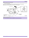
[6] Install and hold the AUTO FOCUS TARGET SLIDE TL-3002 until it is fully seated in the GATE MECHANISM.
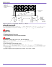
[7] Look through the PROJECTION LENS hole and observe the focus light path on the AUTO-FOCUS TARGET
SLIDE TL-3002. Check that the light image is correct. If not, do the Adjusting the FOCUS LIGHT PATH.
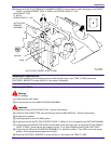
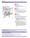
[8] Check that the TAB on the CLAMP PAD ASSEMBLY is in the NULL position. If the TAB is not in the correct
position, do the adjustment procedure for the NULL.
[9] Bend the PHOTOCELL BRACKET to move the NULL in the center; use T-BAR TL-3003.
A091_4026HA
AUTO-FOCUS TARGET SLIDE TL-3002
light path
image
SPRING HOOK TL-1165
ADJUSTMENT TOOL
ASSEMBLY
BRACKET
AUTO FOCUS
TL-3005 or
A091_4026HCA