KRAMER ELECTRONICS LTD.
20
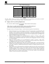
14.1 Power and Indicators
Problem Remedy
No Power
1. Confirm that the rocker switch is in the “ ON” position, and that the lamp is
illuminated.
2. Confirm that power connections are secured at the amplifier and at the
receptacle. Make sure the receptacle is active, outputting the proper mains
voltage.
3. If there is still no power, check the fuse. Remove power cord from the AC
outlet and from the machine and then, using a flat head screwdriver, remove
the fuse holder located directly below the power connector. Confirm that the
fuse is good by looking at the wire connected to the ends of the fuse. If the
wire is broken, replace the fuse with another, with the same value.
14.2 Video Signal
Problem Remedy
No video at the output device,
regardless of input selected.
1. Confirm that your sources and output device are powered on and connected
properly. Video signals connected to the input of your switcher should be of an
identical signal format at the output of your source. Video signals at the output
of your switcher should be of an identical signal format as at the input of your
display or recorder.
2. Confirm that any other switchers in the signal path have the proper input and/or
output selected.
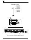
3. Use the Video Tester to test the video path leading to/from your switcher (see
section 4.1 " Video Tester")
Video level is too high or too dim.
1. Verify that the video line is well interfaced through 75ohm impedance,
otherwise it results in a video level that is too high or too dim when looping is
performed and the termination switches are not in proper position.
2. Confirm that the connecting cables are of high quality, properly built and
terminated with 75ohm BNC connectors. Check level controls located on your
source input device or output display or recorder.
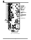
Weak switcher input signals The switcher contains two internal trimmers, accessed via two holes in the base of
the switcher. These allow, if necessary, to adjust switcher output signal level. For
example, if you are using a long cable with heavy losses, you can compensate for it
by fine tuning the signal using the two trimmers. One trimmer adjusts the gain of
the whole video signal and the other adjusts only the high frequencies of the video
which have been degraded by a low quality cable. The hole closer to the power
socket controls the cable compensation the other controls the video level.
WARNING!
Do not use the trimmers except in cases where the cable losses
result in poor resolution of detail or when the whole signal level crashes.
Once they have been touched, the accurate signal transparencies that have been
fine-tuned in the factory are lost. To readjust to the original signal status you need
a stable signal generator and a good quality signal analyzer.


