


-23-
4. LED Indicators
4.1 LED Panels
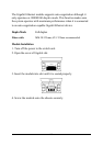
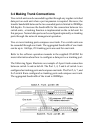
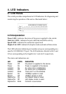
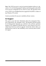
The switch provides comprehensive LED indicators for diagnosing and
monitoring the operation of the unit as illustrated below:
4.2 Interpretation
Power LED : indicates the status of the power supplied to the switch.
Link/Act. LED : indicates the port cable link and traffic activity.
Speed LED : indicates the connection speed used
Duplex/Col. LED : indicate the duplex mode used and collision status
The LED indicators labeled a port number on top are corresponding to a
specific 10/100BASE-TX port. The LED indicators labeled with G1 and
G2 are corresponding to the Gigabit slot 1 and slot 2 respectively.
The states and indications are:
LED STATE INDICATION
Power Off No power is supplied to the device.
Power On Power is supplied to the device.
Link/Act. On An active link is established.
Link/Act. Off No active link is established.
Link/Act. Blink There are Tx or Rx activities.
Speed On 100Mbps speed is used.
Speed Off 10Mbps speed is used.
Duplex/Col. On Full duplex mode is used.
Duplex/Col. Off Half duplex mode is used.
Duplex/Col. Blink Collision occurrences