


6
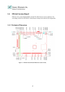
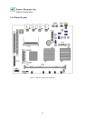
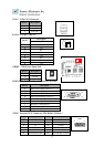
1.4.3 Jumper Settings and I/O Connector
The onboard jumper settings and I/O connector of EM-661 are custom-tailored to fit the
FW-6420 functionality. Changing the jumper settings may result in system malfunction or
unforeseen damages.
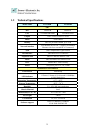
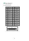
Jumper Settings and I/O Connector Summary for EM-661
JUMPER FUNCTION
CMOS1 Clear CMOS Data
PLRS1 Power LED,HD LED, Reset, Speaker Connector(11 Pin 2.54mm)
FAN1 3 Pin Fan Connector
LAN1-4 LAN Connector
PRJK1 3 Pin Power Input Jack
COMA1 RS-232 Serial Port #1 Connector ( D-Sub )
PKMB1 PS/2 Keyboard & Mouse Connector
VGAB1 External VGA Connector ( Header )
LPTA1 Parallel Connector
USBB1 Dual USB Connector
CF1 Compact Flash Connector
IDEB1 IDE Interface Connector
PCIB1 124 Pin Mini PCI Socket
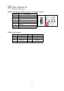
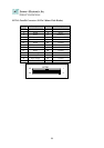
1.4.4 Connector Pin Assignments
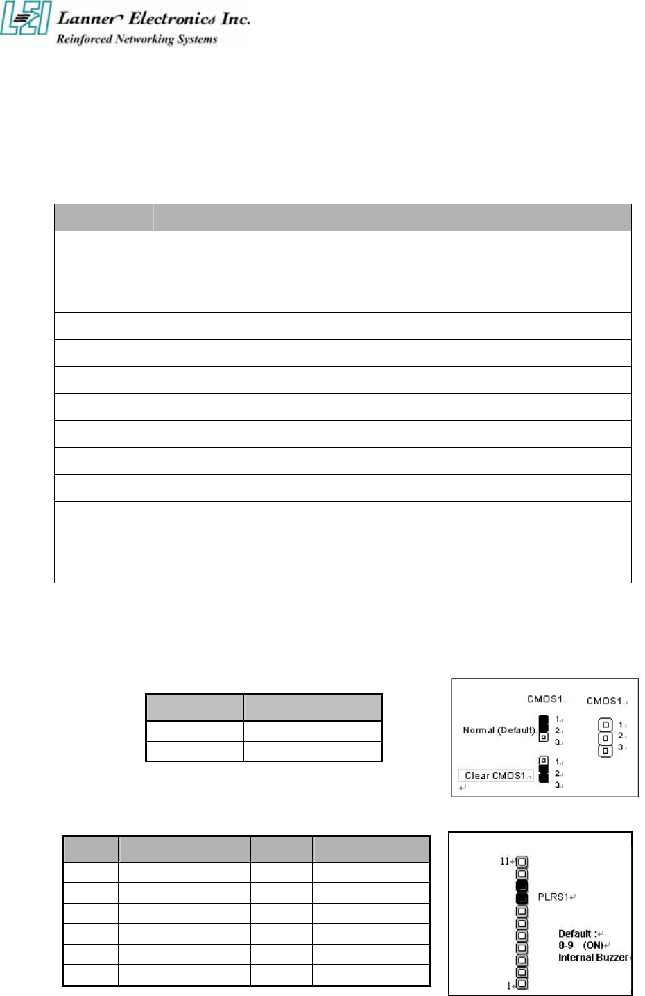
CMOS1:Clear CMOS Data
COM1 Description
1-2 Normal (Default)
2-3 Clear CMOS
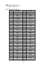
PLRS1:Power LED,HD LED, Reset, Speaker Connector(11 Pin 2.54mm)
Pin No. Description Pin No. Description
1 Power LED + 2 Power LED -
3 Ground 4 HDD LED +
5 HDD LED - 6 RESET SW +
7 RESET SW – (GND) 8 External Speaker -
9 Internal Buzzer - 10 NC
11 External Speaker +