


5
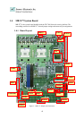
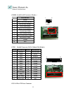
1.4.2 Jumper Settings and I/O Connector
The onboard jumper settings and I/O connector of MB-X77 are custom-tailored to fit the
FW-7890 functionality. Changing the jumper settings may result in system malfunction or
unforeseen damages.
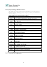
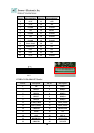
Jumper Settings and I/O Connector Summary for MB-X77
JUMPER FUNCTION
PLRS1 Power LED,HD LED,Reset,Speaker Connector(11 Pin 2.54mm)
PKMB1 PS/2 Keyboard & Mouse Connector (2x4 Header 2.54 mm)
CMOS1 Clear CMOS Data
IDEB1 IDE Interface Connector (40 Pin 2.54mm Pitch Header)
FAN 1 -3 3 Pin FAN Connector
FAN 4- 6 3 Pin FAN Connector
CF1 Compact Flash Connector
COMB1 Serial Port #2 Connector (Header)
LPTA1 Parallel Connector (26 Pin 2.00mm Pitch Header)
PSC1 24 Pin ATX Power Connector
PCIB1 124 Pin Mini PCI Socket
PCIXA1 184 Pin 3V PCIX Socket
PS4S1 - 2 4 Pin Power Connector
PS8P1 8 Pin Power Connector
SATAB1 180 SATA Connector
VR1 Control Sound
PME1 One PME1 Connector supports Wake-on-LAN
LUSBCOM1 BOX_HEADER_2X20_2.00_DIP
PCIEA1 -3 PCI EXPRESS CONNECTOR
USBF1 USB Port#1 & #2 Connector 2x5 Pin 2.54mm
PSWB1 ATX Power As AT Power Use Power Button
REDP1 2 Pin header for Redundant Power detect signal
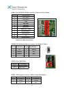
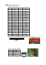
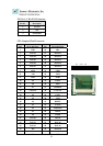
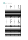
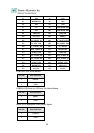
1.4.3 Connector Pin Assignments