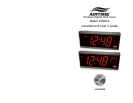
ATDDC4 Series Installation & User’s Guide
Page 2
Clock Installation
Tools required for mounting the clock:
• Drill with a 5/16" bit
• Hammer
• Phillips head screwdriver
• Wall anchors
• Pencil
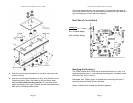
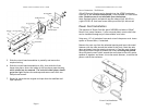
Separate the electronics from the enclosure and to set the Time
Display Format (12hr / 24hr). To do this, remove the plastic end caps,
each secured with two Phillips-head screws. Slide the front lens out of
the front track, then slide the circuit board and display out of the
second track in the enclosure. Carefully place each down on a smooth,
clean surface.
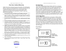
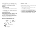
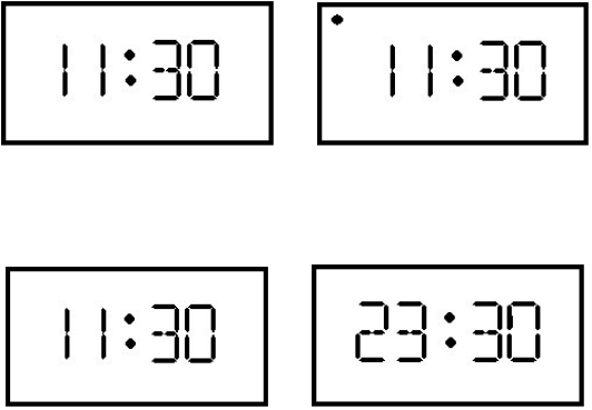
Time Formats
The ATDDC4 Series Wall Clocks can display either 12 Hour or 24 Hour
format. When in 12 Hour format, a red LED in the upper left corner of
the display indicates PM hours. When in 24 Hour format, the hours are
displays in Military style.
12 Hour Format
AM PM
24 Hour Format
AM PM
ATDDC4 Series Installation & User’s Guide
Page 11
Specifications
Dimensions 6 3/4" H X 15 1/2" W X 3 1/8" D
17.1 cm H X 39 cm W X 7.9 cm D
Weight 9 lbs. (4.086 kg)
Display 4-Inch 7-Segment LED for Hours and Minutes
2-inch 7-Segment LED for Seconds (optional)
Housing Extruded aluminum main case with black textured
paint, molded plastic end caps with black texture.
Line Power 120VAC, 80mA typical
24vAC, 400mA typical (optional)
FCC Conforms to FCC Part 15
Environment 32
o
to 140
o
F (0
o
to 60
o
C)
95% Relative Humidity (non-condensing)
Mounting Wall (surface)
Single Gang Box (surface)
Double Face (wall or ceiling) (optional)
Ordering Options
ATDDC4 Wireless Digital Clock, 4 Digits (HH:MM), 120vAC
Optional 6 Digit display (HH:MM:SS)
Optional 24vAC Input
VSE0050 120vAC Power Cord Kit
SAM0625 Double Wall-Mounting Kit
SAM0626 Double Ceiling-Mounting Kit
VIS1551-L Pre-Drilled End Panel (Left)
VIS1551-R Pre-Drilled End Panel (Right)


