


ATDDC4 Series Installation & User’s Guide
Page 8
5. Slide the circuit board assemblies in partially and secure the
required wiring.
6. Slide the circuit board assemblies in fully, then slide the front
lenses into place. Note: the inside of the lens has a paper backing
which should not be removed. The end with wider paper should
go to the right. Replace the end caps and secure each with two
Phillips head screws.
7. Discard or store the two original end caps that the modified end
caps replaced.
ATDDC4 Series Installation & User’s Guide
Page 5
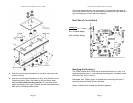
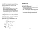
Power Connection – Wall Mount
120vAC Electrical Supply can be brought into the ATDDC4 enclosure
from any of the six vent-hole positions, from the back, or from either
side. Conduit access is not available from the bottom.
Note: Optional plastic end-panels may be ordered (left VIS1551-L),
(right VIS1551-R) that have access holes pre-drilled for side access
.
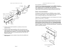
Power Cord Installation
The optional AC Power Cord Kit (part# VSE0050) includes a 120vAC
Power Cord, metal fastener, 2 wire nuts and plastic strain relief that
can be installed through any of the available vent holes.
Strip away 1/2" of insulation from each wire of the power cord. Leave
eyelet on Ground Wire, if attached.
Remove the vent cap from the selected opening and insert the metal
fastener with the tabs toward the inside of the clock. Bend the tabs
down and away from the opening to secure it. Feed the cord through,
allowing sufficient length to attach the wires; including the ground.
Wrap the plastic strain relief around the cord close to the entry point,
squeeze it together and insert it into the metal fastener, to secure the
power cord to the enclosure.
Power Cord Installation