


Digital Display Wall Clock Guide Page 18
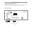
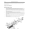
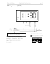
DDC2 (Double Mount - Ceiling)
Note: Make sure you have at least 10 1/2" of side clearance on one side in order to remove the lens and
circuit board assembly.
» Remove the four phillips head screws from the left and the right end caps of the two DDC2 clocks
and remove. Slide the lenses and circuit board assemblies out of the cases and set aside.
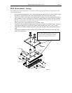
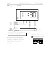
» Place the two DDC2 clocks back to back and secure by inserting a #10 screw through the two key
holes and the two lower mounting holes using lock washers and nuts supplied with the mounting
kit. Note: At this point, if the DDC2 clocks will be mounted too near a wall on one side to secure
the end caps, install the "wall side" end caps now.
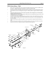
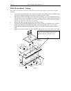
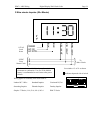
» Remove the center vent cap from the top of each DDC2 clock.
» Line the two posts from the mounting plate up with the vent holes of the DDC2 clocks. Insert the
chase nipples through the vent holes and secure to the mounting plate with a 15/16" wrench.
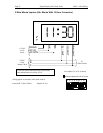
» Slide the circuit board assemblies in partially. Secure the required wiring and install the battery if
used.
» Slide the circuit board assemblies in fully along with the lenses. Install the end caps and secure
each with its four screws.
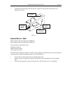
mounting plate
#10 screws
#10 lock washers
mounting plate
DDC2 cases
#10 screws
#10 hex nuts
#
10 lock washers
chase nipple
c
hase nipple
Figure 6
N
ote: When mounting DDC2 clocks, the
short side of the mounting plate must be
p
arallel to the long side of the clocks