


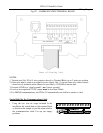
LTRx-512 Installer’s Guide
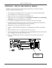
Wiring Diagrams
42
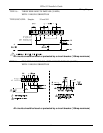
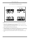
APPENDIX D - WIRING DIAGRAMS
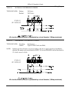
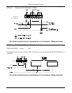
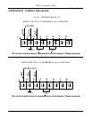
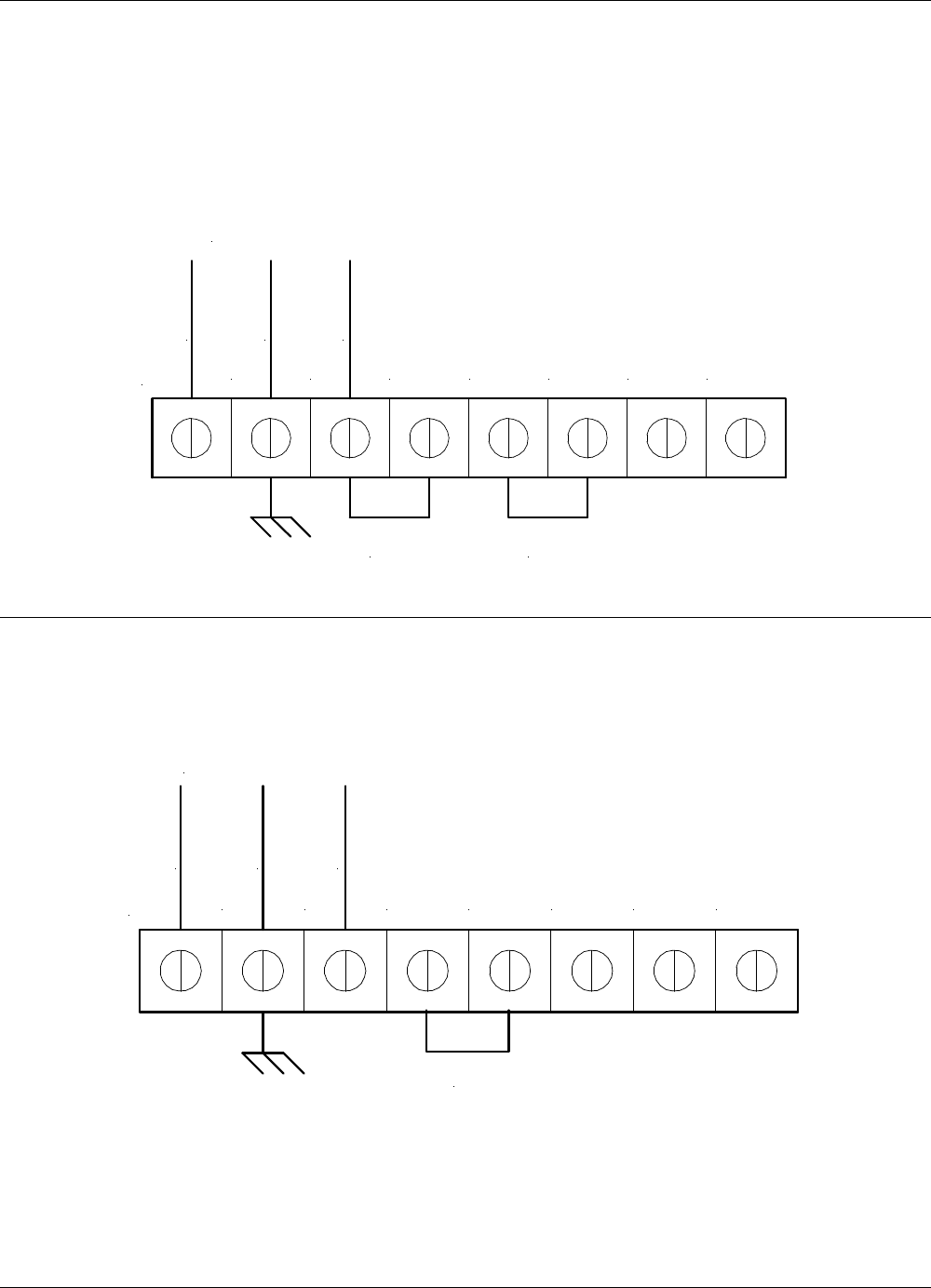
Fig. D1 - TERMINAL BLOCK ‘P4’
WIRING THE LTRx-512 FOR 120VAC (nom.) OPERATION
1
2 3 4 5 6 7 8
J1 J2
WHT
GRN
BLK
120 VAC
All circuits should be fused or protected by a circuit breaker (10Amp maximum)
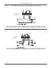
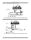
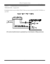
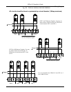
WIRING THE LTRx-512 FOR 220/240VAC (nom.) OPERATION
1
2 3 4 5 6 7 8
J1
WHT
GRN
BLK
220/240 VAC
All circuits should be fused or protected by a circuit breaker (10Amp maximum)