


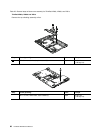
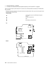
Table 24. Removal steps of system board, DC-in connector, fan, and ExpressCard slot assembly for ThinkPad X200,
X201, and X201i (continued)
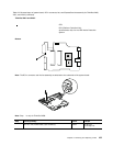
Step Screw (quantity) Color
Torque
1
M2 × 3.5 mm, at-head, nylon-coated (1) Silver
0.181 Nm
(1.85 kgf-cm)
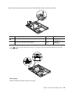
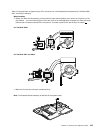
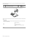
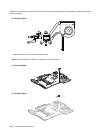
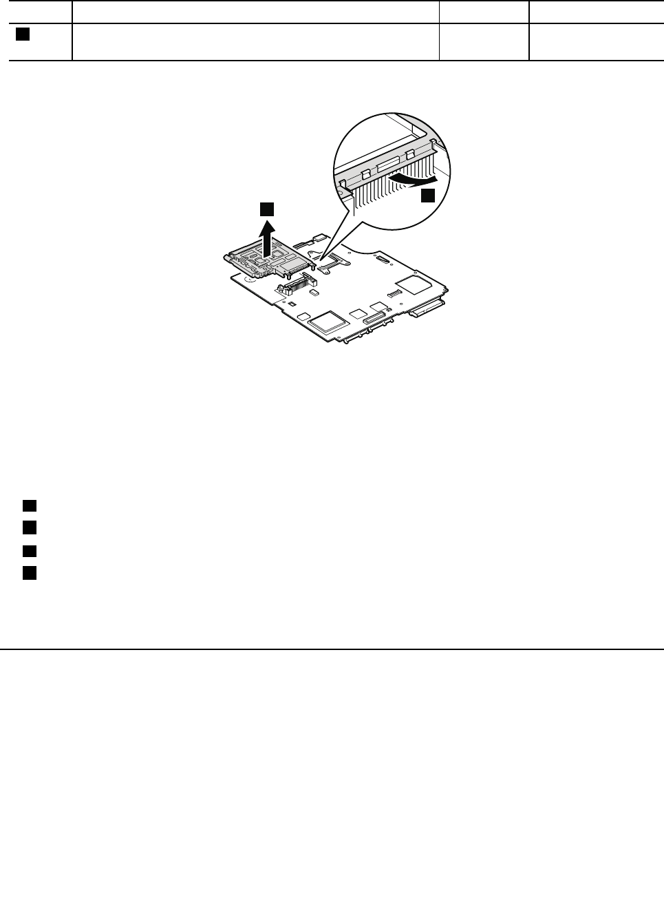
Turn the system board over, and then remove the ExpressCard slot assembly from the system board.
3
2
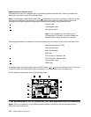
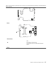
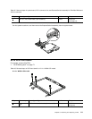
Table 25. Removal steps of system board, DC-in connector, fan, and ExpressCard slot assembly for ThinkPad X200s and
X201s
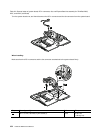
ThinkPad X200s
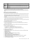
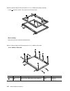
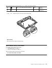
Following components soldered on the system board are extremely sensitive. When you service the system board,
avoid any kind of rough handling.
a
ICH (I/O Controller Hub)
b
CPU
c
MCH (Memory Controller Hub)
d
Accelerometer chip for the HDD Active Protection
System
Top
106 Hardware Maintenance Manual