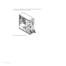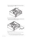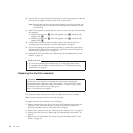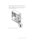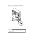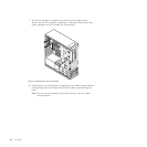
10. Position the new heat sink and fan assembly on the microprocessor so that the
four screws are aligned with the holes in the system board.
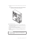
Note: Position the new heat sink and fan assembly so that the heat sink and
fan assembly cable is toward the microprocessor fan connector on the
system board.
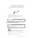
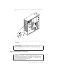
11. Follow this sequence to install the four screws to secure the new heat sink and
fan assembly:
a. Partially tighten screw 1, then fully tighten screw 2, and then fully
tighten screw 1.
b. Partially tighten screw 3, then fully tighten screw 4, and then fully
tighten screw 3.
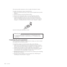
12. Connect the heat sink and fan assembly cable to the system board. See
“Locating parts and connectors on the system board” on page 11.
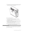
13. If you are replacing heat sink and fan assembly 2, reinstall the optical drive
bracket into the chassis. Then, reinstall the optical drive into the chassis. See
“Replacing the optical drive” on page 29.
14. Reinstall the PCI card holder. See “Removing and reinstalling the PCI card
holder” on page 16.
What to do next:
v To work with another piece of hardware, go to the appropriate section.
v To complete the installation or replacement, go to “Completing the parts
replacement” on page 40.
Replacing the front fan assembly
Attention
Do not open your computer or attempt any repair before reading and
understanding the “Important safety information” in the ThinkStation Safety
and Warranty Guide that came with your computer. To obtain a copy of the
ThinkStation Safety and Warranty Guide,goto:
http://www.lenovo.com/support
This section provides instructions on how to replace the front fan assembly.
Note: Not all computers have the front fan assembly.
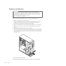
To replace the front fan assembly, do the following:
1. Remove all media from the drives and turn off all attached devices and the
computer. Then, disconnect all power cords from electrical outlets and
disconnect all cables that are connected to the computer.
2. Remove the computer cover. See “Removing the computer cover” on page 13.
3. Remove the front bezel. See “Removing and reinstalling the front bezel” on
page 15.
4. Remove the PCI card holder. See “Removing and reinstalling the PCI card
holder” on page 16.
34 User Guide


