Note: Use only the screws provided by Lenovo.
9. Install and tighten the four screws at the rear of the chassis to secure the
power supply.
10. Check the position of the voltage-selection switch on the rear of the computer.
Use a ballpoint pen to slide the switch, if necessary.
Note: Some computers do not have a voltage-selection switch. These
computers automatically control the voltage.
v If the voltage supply range is 100–127 V AC, set the switch to 115 V.
v If the voltage supply range is 200–240 V AC, set the switch to 230 V.
11.
Reconnect all the power supply cables to the drives and the system board.
12. Go to Chapter 4, “Completing the parts replacement,” on page 35.
Replacing the heat sink and fan assembly
Attention
Do not open your computer or attempt any repair before reading the “Important safety
information” in the ThinkCentre Safety and Warranty Guide that came with your computer.
To obtain a copy of the ThinkCentre Safety and Warranty Guide, go to:
http://www.lenovo.com/support
This section provides instructions on how to replace the heat sink and fan
assembly.
To replace the heat sink and fan assembly:
1. Open the computer cover. See “Opening the cover” on page 12.
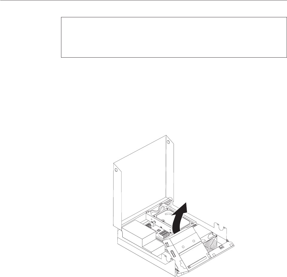
2. Pivot the drive bay assembly upward to gain access to the heat sink and fan
assembly.
Figure 18. Accessing the heat sink
Chapter 3. Installing options and replacing hardware 23


