


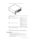

1. Remove the computer cover. See “Removing the cover” on page 10.
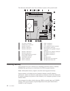
2. Locate the memory connectors. See “Identifying parts on the system board” on
page 11.
v If the two memory connectors closest to the edge of the system board are a
yellow color, your system board has DDR type memory. DDR memory
modules are 184-pin, 2.5 V and can be used in any combination of 128 MB,
256 MB, 512 MB, and 1 GB sizes.
v If the two memory connectors closest to the edge of the system board are a
green color, your system board has DDR2 type memory. DDR2 memory
modules are 240-pin, 1.8 V and can be used in any combination of 256 MB,
512 MB, and 1 GB sizes.
Notes:
a. The type of memory required is also indicated in text near the logo on
the system board.
b. System memory as reported in the ″System Summary″ section of the
Setup Utility or the operating system might be less than the amount of
physical memory installed. This discrepancy is due to memory
addressing limitations of the Intel 915G Family chipset, and is usually not
visible until more than 3.0 GB of memory is installed.
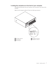
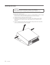
To
install a memory module:
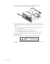
1. Remove the computer cover. See “Removing the cover” on page 10.
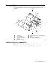
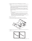
2. Pivot the drive bay assembly upward to gain access to the system board.
*XXXXXXXXX*
*XXXXXXXXX*
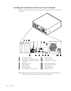
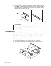
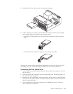
3. Locate the memory connectors. See “Identifying parts on the system board” on
page 11.
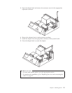
4. Open the retaining clips.
Chapter 1. Installing options 13