


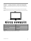
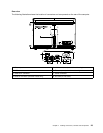
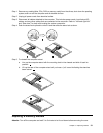

Identifying parts and connectors on the hardware TV scale board
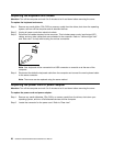
The following illustration shows the locations of parts on the analog hardware TV board.
1
2
3
6
4
5
1. LVDS Connector 4. TV Function Connector
2. Converter Connector 5. Fan Connector
3. Mother Board Connector
6. Debug Port
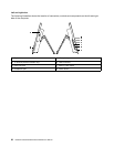
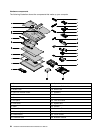
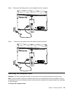
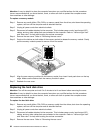
The following illustration shows the locations of parts on the digital hardware TV board. (ATS-C type)
1
2
3
6
7
4
5
1. LVDS Connector 5. Tuner Board Connector
2. Converter Connector
6. Debug Port
3. TV Function Connector 7. Fan Connector
4. Mother Board Connector
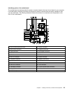
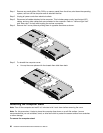
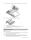
The following illustration shows the locations of parts on the digital hardware TV board. (DVB-T type)
1
2
3
6
7
4
5
1. LVDS Connector 5. Tuner Board Connector
2. Converter Connector 6. Fan Connector
3. TV Function Connector
7. Debug Port
4. Mother Board Connector
26 IdeaCentre B540–B540PHardware Maintenance Manual