


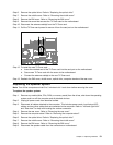
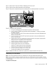
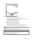
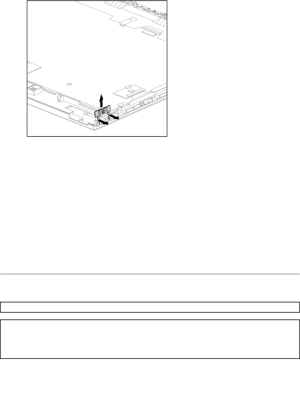
Step 27. Disconnect the cable from the power switch board.
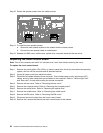
Step 28. To install the new the power switch board:
a. Connect the power switch cable to the power switch board.
b. Insert the power switch board, snap it in position and secure it with the pins.
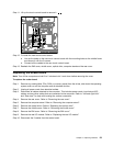
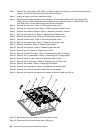
c. Line up the chassis with the front bezel and reconnect the power board, front function board,
front indicator board and LED cables to the chassis.
d. Reattach the Wi-Fi antenna cables back to the front bezel.
e. Connect the converter cable to the LED panel.
f. Reconnect the touch cable to the touch control board.
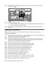
g. Secure the new LED panel to the chassis with 4 screws.
h. Secure the chassis to the front bezel with the 9 screws.
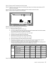
i. Reinstall the motherboard, camera, TV-Tuner card, Wi-Fi card, TV scalar board, rear I/O
module, CPU, heat-sink, battery, system fans and the memory modules.
Step 29. Reattach the EMI cover, middle cover, optical drive, computer stand and the rear cover.
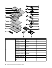
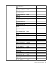
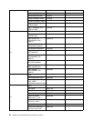
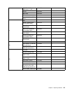
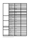
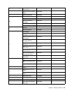
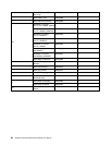
FRU lists
This chapter lists the information on the eld replaceable units (FRUs).
Attention: Be sure to read and understand all the safety information before replacing any FRUs.
Notes: FRUs that have a 1 or 2 in the CRU column are Customer Replaceable Units (CRUs).
• 1– identies parts that are fairly simple to replace, requiring few or no tools.
• 2– identies parts that are slightly more difcult to replace.
• N-identies parts that are not to be replaced by the customer.
Chapter 8. Replacing hardware 59