


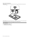
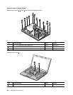
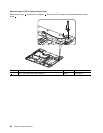

Removal steps of system board assembly
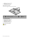
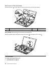
Remove the screws 1 , and then detach the connectors as shown in the following illustration.
4
5
2
3
1
1
1
Step Screw (quantity) Color
Torque
1
M2 × 3 mm, at-head, nylon-coated (3)
Black
1.85 kgfcm
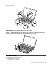
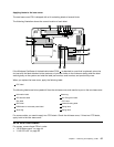
When installing: Make sure that all the connectors are attached rmly.
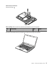
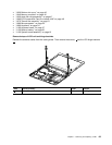
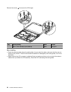
Remove the system board in the direction shown by the arrow 6 . Then detach the DC-in cable 7 .
7
6
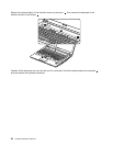
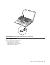
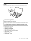
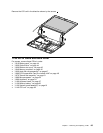
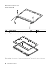
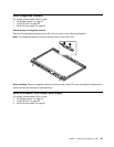
1140 LCD unit
For access, remove these FRUs in order:
• “1010 Battery pack” on page 44
• “1020 Optical drive” on page 44
62 Hardware Maintenance Manual