


• “1030 Bottom slot cover” on page 46
• “1040 Memory modules” on page 46
• “1050 Hard disk drive assembly” on page 47
• “1060 PCI Express Mini Card for wireless LAN” on page 49
• “1070 Thermal fan assembly” on page 51
• “1080 Microprocessor” on page 53
• “1090 Keyboard” on page 54
• “1100 Keyboard bezel” on page 57
• “1120 Backup battery” on page 60
• “1130 System board assembly” on page 61
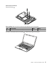
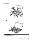
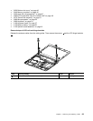
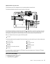
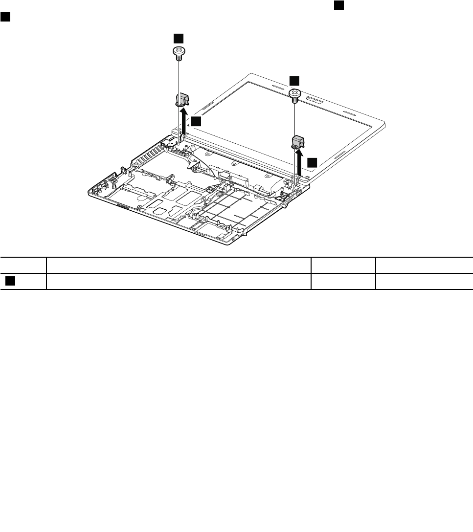
Removal steps of LCD unit and hinge brackets
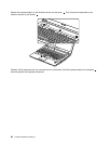
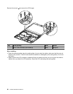
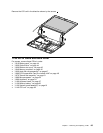
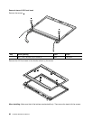
Release the antenna cables from the cable guides. Then remove the screws 1 and the LCD hinge brackets
2 .
1
2
2
1
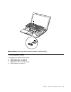
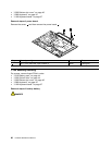
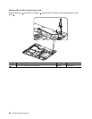
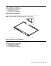
Step Screw (quantity) Color
Torque
1
M2 × 3 mm, at-head, nylon-coated (2)
Black
1.85 kgfcm
Chapter 7. Removing and replacing a FRU 63